Tag Archives: dc motor brushless

China 2023 New high-performance BLDC motor Z4BLD60 brushless DC geared motor compact worm gearbox

Error:获取返回内容失败,
Your session has expired. Please reauthenticate.
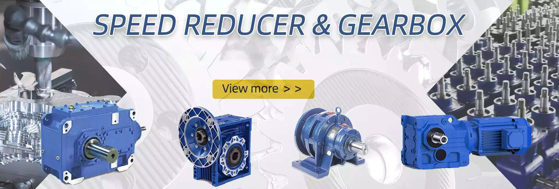
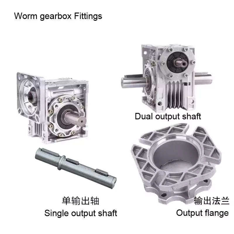
worm reducer

What is a worm gear reducer gearbox?

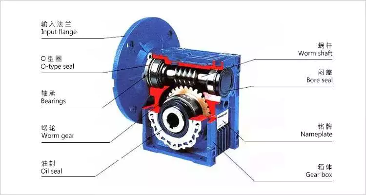
The worm gear reducer gearbox is used to change the output speed of the mechanical device. It consists of worm and helical gears mounted on the input side of the equipment. In some cases, this gear reduction system can be multi-stage, enabling extremely low output speeds. It has the advantages of low energy consumption and low vibration.
Hollow shaft worm gear reducer gearbox

Worm gear reducer gearbox is an effective device to reduce the speed of mechanical equipment. The use of hard steel or non-ferrous metals for the worm increases its efficiency. Worms made of hard steel generate more heat than worms made of mild steel. Different thermal expansion results in gaps between mating surfaces. Despite its many benefits, worm gear reducer gearboxes are prone to oil leakage, which can be a problem for a number of reasons.
Hollow shaft worm gear reducer gearboxes are available in different gear ratios and are compatible with many motor types. Some are available in dual-axis and single-axis configurations and can be mounted horizontally or vertically. They are also available in intermediate ratios, as well as four- and five-speed transmission types. They can also be connected with additional output shafts.
Another type of worm gear reducer gearbox is the multi-stage variety. This gear reducer gearbox has multiple stages, enabling it to reduce speed with extremely low output speeds. In addition to the large transmission ratio, the multi-stage gear reducer gearbox has low noise, low vibration and low energy consumption.
Worm gear reducer gearboxes offer space-saving solutions as well as increased torque. Agknx Gearbox offers worm gear reducer gearboxes that solve common deceleration problems. The company has also expanded its product range into the bathroom market. Compared with the standard gearbox, the worm gear reducer gearbox has the characteristics of lower price and better torque output.
Agknx worm gear

The Agknx type worm gear reducer gearbox has multi-tooth line contact and is widely used in heavy machinery. These gears are characterized by a high load-carrying capacity, but they are highly sensitive to misalignment and manufacturing errors. However, by employing point contact, these gears can be made more reliable and can withstand higher loads.
Another major advantage of the Agknx worm gear is its high load capacity. The tooth profile design of the gears has a high relative slip ratio, which improves efficiency and load capacity. In addition, the large angle between the sliding direction and the contact line provides a low coefficient of friction. The Agknx worm gear also features premium carburized steel and phosphor bronze castings for exceptional durability. In addition, the tooth profile is very precise, the operation is quiet, and the speed fluctuation is small.
Agknx worm gear reducer gearboxes are designed to operate for up to ten hours per day with an even load. The design of this worm gear reducer gearbox stems from Sumitomo Heavy Industries’ extensive experience in gear reducer gearboxes. The smooth surface texture and precise tooth profile of the gears ensure that the gears can withstand high loads without damaging the lubricant film. In addition, Agknx worm shafts are specially designed to have the right stiffness.
Agknx worm gear reducer gearboxes are designed to maximize load capacity while minimizing energy consumption. Its fully meshed teeth reduce surface pressure on the worm gear teeth and increase load capacity.
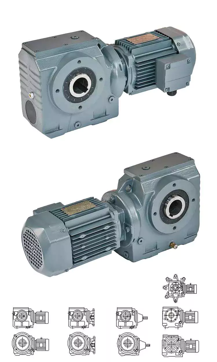
worm reducerDouble throat worm gear

There are a few things to consider when choosing a dual-throat worm gear. First, the diameter of the root circle must match the circle pitch of the larger gear. This measurement is usually done by measuring the distance between adjacent teeth. Alternatively, the worm’s normal module can be used. It is the value entered in the worm module dialog. In addition, the axial pitch of the worm should be equal to the pitch diameter of the circular pitch.
Double-throat worm gears are an excellent choice for heavy and heavy-duty applications. The design of this worm gear is ideal for heavy-duty applications as it provides a tighter connection between the worm and the gear. It is also more compact than other types of gear and is comparable to a fine-pitch lead screw.
The efficiency of a double-throat worm gear depends on the material of the gear and worm. Typically, gears are made of case-hardened steel, while worm gears are made of bronze or cast iron. In some cases, a combination of cast iron and bronze can be used.
The deflection of the worm shaft is also affected by the tooth parameters. Tooth height, pressure angle, and size factors all affect the deflection of the worm shaft. In addition, the number of worm threads is another important parameter that affects the deflection of the worm shaft.
Double-throat worm gears are commonly used in industrial applications where high drive reduction is required. The worm has a concave and internal tooth structure that can be adjusted to achieve various ratios. Worm gears and worm gear assemblies must be properly mounted on their shafts to prevent back drive.
Brass worm gear

The basic working principle of the brass worm gear reducer gearbox is the same as that of the traditional worm gear reducer gearbox. Its axial pitch must be equal to the circumferential pitch of the larger gear. The single-thread design advances one tooth per revolution, while the double-thread design advances two teeth. The threads on the worm are either left-handed or right-handed. The lead of a worm is the distance a point on the thread of the worm moves in one revolution. The lead angle is the angle tangent to the pitch of the cylinder and the axis of the worm.
Double-thread worm gear reducer gearboxes are best for heavy loads. It provides the tightest connection between the worm and the gear. Assembly of the worm gear requires precise mounting. The keyway installation method involves drilling a square cut in the gear hole. This prevents the worm from rotating on the shaft and helps transmit torque. Then use the set screw to secure the gear to the hub.
The large fuel tank helps keep the worm gear clean and reduces heat. It also provides lubrication for extended life. Worm gear reducer gearboxes with oil reservoirs provide a lubricated environment and low-friction surfaces. Additionally, it offers multi-position installation flexibility. Additionally, its housing is cross-milled for precise alignment. It also features internal baffles for leak-free ventilation.
I260 series worm gear reducer gearboxes are one-piece iron casings with solid or hollow output shafts and tapered roller bearings. This gear reducer gearbox is designed for low to medium-horsepower applications. This gear reducer gearbox is a cost-effective option with low initial cost, the high gear ratio, and high torque in a compact package. Also, it is more shock resistant than other gear reducer gearboxes.
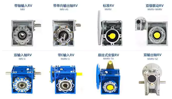
worm reducerBrass worm gear

Brass worm gear reducer gearbox is a reduction gear. This type of gear can provide a lot of reduction in a small package. This type of gear reducer gearbox also has the ability to generate high torque. However, it is important to understand that this gear reducer gearbox has thermal limitations, which reduce its efficiency. The choice of lubricant for this gear reducer gearbox is very flexible. However, being a yellow metal, it is important to remember that the lubricant must be non-reactive.
Worm gears are used in many consumer and industrial applications and have high reduction ratios. These gears are produced in various configurations and sizes. Worm gears are similar to spur gears but have non-parallel shafts. Worm gears are also suitable for applications requiring low output speed but high torque.
Worm gears have some distinct advantages over other gears. First, unlike standard gears, the worm rotates in a worm-like motion. This mechanism prevents reverse movement. This is because the lead angle of the worm gear is small. Additionally, the worms self-lock, helping to prevent reversal. However, this mechanism is not entirely reliable. Worm gears can be found in elevators, fishing reels, sprockets, and automotive power steering.
Another advantage of worm gears is that they are easy to manufacture. The rationale behind this design is to have two mutually perpendicular axes. Then, two or more threads are added to the worm gear. The common tangent between these two shafts intersects the pitch line of the worm gear shaft. This is the basis of transfer speed.

China 2023 New high-performance BLDC motor Z4BLD60 brushless DC geared motor     compact worm gearboxChina 2023 New high-performance BLDC motor Z4BLD60 brushless DC geared motor     compact worm gearbox
editor by Cx 2023-07-06

China High Efficiency Worm Gear Reducer Gearbox for Mining Transportation Electric Cars brushless dc motor worm gearbox

Product Description

Product Description

Merchandise Parameters

Packaging & Delivery

Company Profile

US $100-500
/ Piece
|
1 Piece

(Min. Order)

###

Application: Motor, Electric Cars, Motorcycle, Machinery, Marine, Toy, Agricultural Machinery, Car
Hardness: Hardened Tooth Surface
Installation: Vertical Type
Layout: Coaxial
Gear Shape: Conical – Cylindrical Gear
Step: Single-Step

###

Samples:
US$ 60/Piece
1 Piece(Min.Order)

|
Request Sample

###

Customization:

Worm gear reducer gearbox

A worm gear reducer gearbox is a mechanical device used to reduce the viscosity of fluids. It can be used in a variety of applications and is available in a variety of sizes. Read on to learn more about these devices. They come in different shapes, sizes and prices. Also, these products are very reliable.
worm reducer

Viscosity

A new study shows that polymers derived from worms reduce the viscosity of aqueous solutions. The researchers mixed the worms with water and then applied shearing force to the mixture. Polymer-filled solutions are more resistant to shear forces than simple liquids. This is because when the solution is sheared, the filaments become entangled with each other. When the solution is sheared, the filaments line up, reducing the viscosity of the solution.
The researchers then used live insects to study the polymer’s shear thinning properties. By measuring “worm activity”, the researchers could calculate the viscosity of the mixture. The researchers then altered the worms’ activity and measured changes in the viscosity of the mixture.
The PSMA13 precursor was synthesized from BzMA at 90 °C. The resulting PSMA13-PBzMA65 worms were studied using SAXS, 1H NMR and TEM. They were found to be highly anisotropic over a wide temperature range.
The efficiency of a worm gear reducer gearbox increases with the number of revolutions of the input shaft. Braking torque also increases with the viscosity of the oil. These three factors are used to determine the efficiency of a worm gear reducer gearbox. A worm gear reducer gearbox with a helical pinion on the motor shaft will achieve a 40:1 gear ratio. The combination of a 4 liter ratio helical primary gear with a 10:l worm secondary gear will achieve high efficiency and overload capability.
The PSMA13-PBzMA65 dispersion has the same effective viscosity at 20 degrees Celsius and variable temperature. The transition time is 0.01 Pa s, indicating good thermal reversibility.

Self-locking function

Worm reducer gearboxes have many advantages. This gear has a high capacity and can transmit a lot of power. It’s also very quiet. Its advantages also include a space-saving design. Another benefit of worm reducer gearboxes is their ease of lubrication and cooling. It is also an excellent choice for transmitting high power with high gear ratios.
The self-locking function of the worm gear unit ensures that torque is only transmitted in one direction. When the load peaks, the torque signal is disabled. Unlike conventional gear reducer gearboxes, self-locking worm gears are not interchangeable.
Self-locking worm gears are not suitable for high mass applications because the weight of the driven mass can overwhelm the gear. The large mass can cause a huge side load on the worm, which can cause the worm to break. To solve this problem, a self-locking worm gear train with special provisions can be designed to reduce the heat generated.
The self-locking properties of worm reducer gearboxes are helpful in many industrial applications. It prevents reversing, which saves money on the braking system. It can also be used to lift and hold loads. The self-locking function is very useful in preventing backing.
The self-locking function depends on the pitch diameter and lead angle. A larger pitch diameter will make the self-locking function easier. However, the lead angle decreases as the pitch diameter increases. The higher pitch diameter will also make the worm reducer gearbox more resistant to backlash.
Self-locking worm gears are also useful in lifting and hoisting applications. If the worm gear is self-locking, it cannot reverse its direction without positive torque.s This makes the worm gear ideal for applications where the worm must be lowered.
worm reducer

application

The worm gear reducer gearbox market is a global industry consisting of several sub-sectors. This report analyzes past and current market trends and discusses key challenges and opportunities in this market. It also highlights leading marketing players and their marketing strategies. Furthermore, the report covers important segments and provides information on emerging segments.
Worm reducer gearboxes can be used in a variety of applications, such as reducing the speed and torque of rotating parts. These gears are usually available as gear sets and seat units and are available in multi-speed designs. Some manufacturers also offer precision worms and zero-backlash worms for high precision reduction.
Typically, worm gears are used on vertical axes that do not intersect. Compared to other gear drives, they are inefficient but produce a lot of reduction. There are two basic types of worm gears: double envelope and single envelope. The difference is in how they work. When the two axes do not intersect, a double-enveloping worm gear is used.
In the industrial world, worm gear reducer gearboxes are the most popular type of reducer gearbox. They are known for their high torque output multipliers and high reduction ratios. They are used in many power transmission applications including elevators, safety gates, and conveyor belts. They are especially suitable for low to medium-horsepower applications.
Worm gears can also be used for noise control. Its unique shape and size make it suitable for tight spaces. They are also suitable for conveying heavy materials and the packaging industry. In addition, they have high gear ratios, which make them suitable for small and compact machinery.

cost

The cost of a worm gear reducer gearbox depends on several factors, including the type of worm used, the materials used to manufacture the equipment, and the number of users. The worm gear reducer gearbox market is divided into two types: vertical and horizontal. Furthermore, the market is segmented by application, including the automotive industry, shipping industry, and machinery and equipment.
Worm gear reducer gearbox is a popular type of reducer gearbox. They are available in standard and flush-type packaging. They feature C-side inputs for standard NEMA motors and multiple mounting positions to suit the application. For example, a soup factory can use the same hollow reducer gearbox in multiple installation locations.
Another application for worm gear reducer gearboxes is in conveyors. They provide torque and speed reduction to move products efficiently. They are also widely used in security doors that automatically lock when they are closed. Typically, these doors use two separate worm drives. In this way, they cannot be reversed.
The cost of a worm gear reducer gearbox is determined by several factors. Size and material are important. Worm gear reducer gearboxes can be made of aluminum, cast iron, or stainless steel. Its efficiency depends on its size and proportions. It is usually used as a retarder in low-speed machinery, but can also be used as a secondary braking device.
There are two types of worms: standard worm and double worm gear. Standard worms have one or two threads, and double worm gears have one left-hand and right-hand thread. A single-threaded combination will give you a 50 reduction ratio, while a dual-threaded combination will only give you a 25% reduction.
worm reducer

manufacturing

Agknx Transmission Ltd. manufactures premium worm gear reducer gearboxes with robust construction and premium case-hardened steel worms. They use phosphor bronze centrifugally cast rims and attach them to the output shaft in the center. They also feature dual-purpose bearings and a large overhang load margin on the output shaft. The high-quality reducer gearbox also has a full range of positive lubrication functions. This means that they do not need special attention when using low-speed shaft extensions.
China High Efficiency Worm Gear Reducer Gearbox for Mining Transportation Electric Cars     brushless dc motor worm gearboxChina High Efficiency Worm Gear Reducer Gearbox for Mining Transportation Electric Cars     brushless dc motor worm gearbox
editor by czh 2023-01-30

China Hot Sale Quality Machine Gear Box Casting Cast Irom Gearbox Reducer For Driving Motion brushless dc motor worm gearbox

Warranty: 1 a long time
Relevant Industries: Constructing Substance Outlets
Weight (KG): 3 KG
Personalized assist: OEM
Gearing Arrangement: Worm
Output Torque: 1.8-2430N.M
Input Speed: 1400RPM
Output Velocity: 19-186.7RPM
Producing method of equipment: Solid equipment
Toothed Part Shape: Involute spur gear
Colour: silver, blue, black and so on
key word: gearbox WPA
Packaging Details: interior pack: use plastic bag and foam box,gearbox WPA . outer pack: carton or wood circumstance for every established or dependent on customer’s request.

one.Housing:iron cast2. reduced noise(<50DB)3.Model:WPA forty-250,Ratio:10 to 604.Efficient and risk-free operating5.ISO9001,Factory price,OEM6.Technologies Info:

Type:gearbox WPA
Model:WPA 40-250
Ratio:1:10,fifteen,20,twenty five,thirty,40,50,sixty
Color:Blue/Silver Or On Buyer Request
Material:Housing: Die-Solid Iron solid
Worm Equipment-Copper-10-3#
Worm-20CrMn Ti with carburizing and quenching, area harness is 56-62HRC
Shaft-chromium steel-45#
Packing:Carton and Wooden Circumstance
Bearing:C&U Bearing
Seal:NAK OTHER
Warranty:1 Calendar year
Input Electrical power:0.06KW,.09KW
Usages:Industrial Equipment: Food Stuff, Ceramics,CHEMICAL,Packing,Dyeing,Woodworking,Glass.
IEC Flange:56B14, 63B14, 63B5, 63B5, 71B14,80B14 AND SO ON
Lubricant:Synthetic&Mineral
Item Classification Solution Big difference About Us Exhibition Certification Packing&Shipping and delivery FAQ 1.Q:What information need to i tell you to verify the worm gearbox?A:Product/Dimensions,B:Ratio and output torque, C:Powe and flange type,D:Shaft Path,E:Housing colour,F:Order amount.2.What variety of payment approaches do you settle for?A:T/T,B:B/L,C:Money 3.What is actually your guarantee?1 yr. 4.How to shipping?A:By sea- Buyer appoints forwarder,or our income crew finds suited forwarder for customers.By air- Customer gives acquire convey account,or our income team fingds ideal convey for customers.(Mostly for sample) Other- We prepare to supply items to some spot in China appointed by buyers. 5.Can you make OEM/ODM get?Sure,we have abundant expertise on OEM/ODM buy and like indication Non-disclosure Arrangement just before sample making

Worm gear reducer

Cheaper than planetary gearboxes In many cases, worm gear reducers are a popular alternative to planetary gearboxes. A worm gear reducer is a mechanical device with vertical input and output shafts. This allows for very high reduction ratios. They are typically used in high-reduction situations such as machine tools.
Worm gears are cheaper than traditional gearboxes. They also have many benefits, including noise reduction. The output shaft of the worm gear reducer is almost 90 degrees from the motor input shaft, making it ideal for high-torque applications.
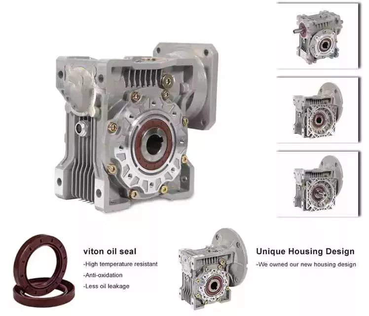
The worm gear reducer adopts an aluminum body, which is light in weight and high in operation efficiency. Additionally, they are available with hollow shafts and mounting flanges. In terms of initial cost, worm gear reducers are cheaper than planetary gearboxes. In addition, they have better efficiency and longer service life.
Worm drives are also ideal for portable battery-powered lifting equipment. The high gear ratio of the worm gear ensures that it does not reverse drive. The worm gear has a spring-applied brake that holds the motor in place.
Planetary gearboxes are popular among industrial users. The efficiency of planetary gearboxes is important for practical applications.
worm_reducer

pocket

The compact worm gear unit consists of a housing with an inner cavity. It has two side walls, one on either side of the front cover (13) and one on both sides of the rear cover (14). The front end cap is screwed onto the housing and the inner cavity is accessed through the rear end cap.
The compact worm gear unit can be configured to suit your application. They have many advantages, including saving space and increasing torque. The range includes single-envelope and double-envelope versions, available in a number of different power ratings. Additionally, they are IP65-rated, making them ideal for applications involving high radial or axial forces.
The compact worm reducer is a simple but effective worm drive. Its worm gear 16 meshes with the output shaft and rotates relatively stably. It also has a front-end cap and rear bearing. This enables the compact worm reducer to reduce vibration without damaging the output shaft.
Compact worm gear reducers are ideal for many applications and offer high efficiency. The compact design means you can mount them on the motor’s flange or base. Its durable construction makes it ideal for a variety of industries. They are extremely durable and can handle high-pressure and washdown conditions. They also come standard with a synthetic shaft.

high efficiency

High-efficiency worm gear reducers are ideal for applications that require precision, repeatability, and efficient performance. These reducers are designed with state-of-the-art servo motor technology to provide tight integration and an angular backlash of less than two arc minutes. The reduction ratio can be lower if the application requires it.
Rising energy costs have led to an increased focus on the efficiency of drives. In response to this, manufacturers have increased the efficiency of worm gear reducers through a number of technical improvements. By minimizing losses from rolling and sliding friction, worm gear reducers are more efficient than their counterparts.
The high-efficiency worm reducer is simple in design and has the characteristics of a compact structure, high-speed ratio, low power consumption, and self-locking. Other advantages of these reducers include low noise and long service life. Many also have built-in control systems that allow manual and remote adjustments. They also feature automatic shutdown protection and thermal protection.
High-efficiency worm reducers can be used for mechanical acceleration. The input hypoid gear is usually made of steel, while the output hypoid gear is usually made of bronze. Bronze is a soft metal that is good at absorbing shock loads. However, bronze requires work hardening to achieve optimum hardness. For large worm gears, this process can take 300 to 550 hours.
worm_reducer

low clearance

A low-clearance worm reducer is a device used to adjust the speed of a rotating shaft. It uses a worm gear consisting of two members. One worm is at one end of the shaft and the other is at the other end. Both worms are screwed into the synchronous drive structure.
Low clearance worm gear reducers can be produced on conventional worm gear production lines without overlapping investments. These units are usually made of soft rubber. Also, they are relatively quiet in operation. These machines are designed so that they are suitable for use in elevators. The softer material in the worm gear also helps absorb shock loads.
The tooth profile of the worm gear is designed to change with the axial movement of the worm. Worms have thinner right teeth and thicker left teeth. As the worm moves to the right, its teeth mesh with the worm gear, reducing backlash.
There are many different types of worm gears. The design of gears depends on many factors, including backlash, thermal design, friction factors and lubrication. Worm gears are made of several different materials. Some different types of materials used in worm gears require special lubrication.

quieter

The quieter worm reducer is designed to reduce the noise level of the rotating gear motor. The device has more gear teeth in meshing contact with the gears, which helps it run more quietly. In addition to being quieter than other transmissions, it’s also less expensive than its counterparts.
Worm gearboxes can be used for different applications, but they are not as efficient as helical gearboxes. Worm reducers are cheaper but less than 90% efficient. Higher gear ratios reduce efficiency, so worm gear reducers are better suited for applications that require low-speed torque. The cost of buying a worm gearbox will depend on the horsepower and gear ratios required.
Worm reducers are also more comfortable to use than planetary gearboxes. They don’t vibrate and heat up quickly, making them an excellent choice for low to medium horsepower applications. Worm gear reducers can be upgraded to improve their performance by combining with other gear trains or gearboxes.
worm_reducer

easy to replace

An easily replaceable worm gear reducer can save you a lot of money. A worm gear reducer is part of a chain drive and allows you to change gear ratios quickly and easily. Worm gear reducers can be easily replaced in a number of ways. It’s a good idea to read the manufacturer’s manual before replacing a worm gear reducer. Make sure you have the instructions available so you can refer to them in the future.
Worm gear reducers offer many advantages, including long service life and low noise. They are also designed with a 90-degree output shaft for easy installation. Another advantage of these gear reducers is that they can be used with both solid and hollow output shafts. This means less maintenance and downtime.
Worm gear reducers are widely used. Most gear manufacturers have large inventories. Worm gears also have uniform mounting dimensions. Dimensional consistency means you don’t have to worry about matching the shaft length and diameter to the worm gear. You can easily find a replacement worm gear reducer for your equipment.
When replacing the worm gear reducer, check the lubricating oil recommended by the machine. If not included, use original gear oil. Be sure to follow the manufacturer’s instructions carefully.

China Hot Sale Quality Machine Gear Box Casting Cast Irom Gearbox Reducer For Driving Motion     brushless dc motor worm gearboxChina Hot Sale Quality Machine Gear Box Casting Cast Irom Gearbox Reducer For Driving Motion     brushless dc motor worm gearbox
editor by czh

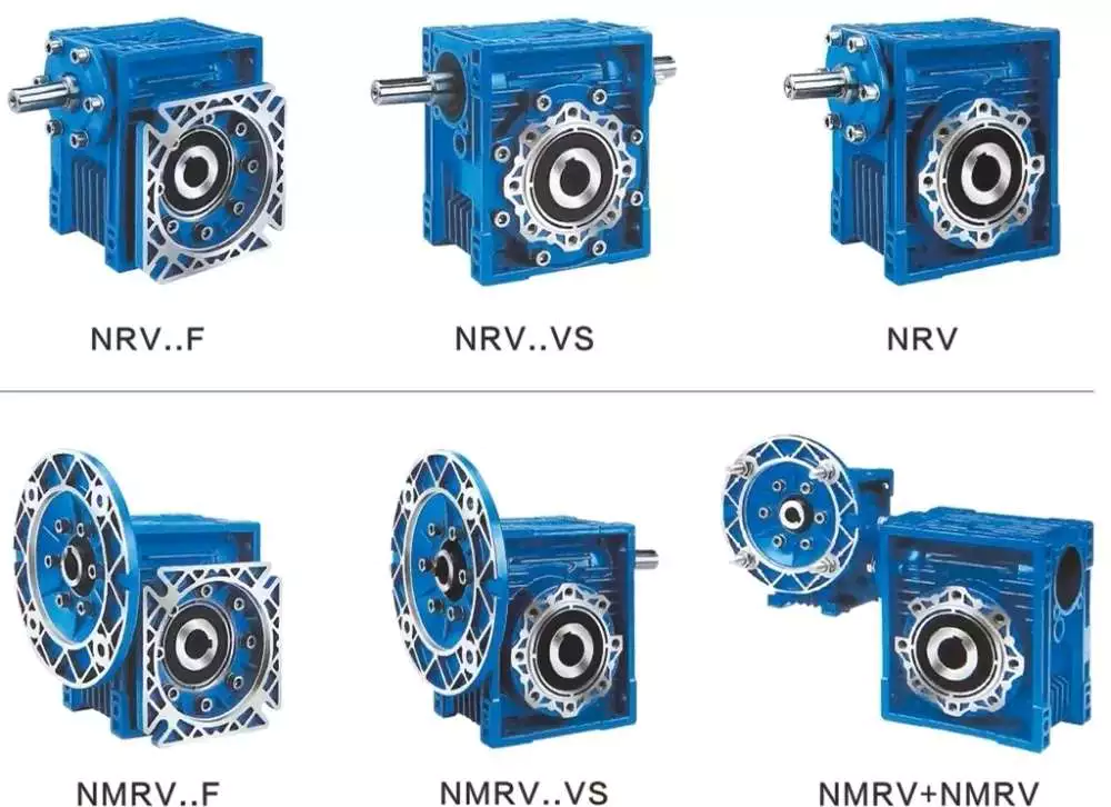
China Standard NMRV +NRV small Worm Gear Reducer Worm Gearboxes brushless dc motor worm gearbox

Warranty: 1 year
Applicable Industries: Hotels, Garment Shops, Building Content Shops, Production Plant, Machinery Mend Retailers, Foods & Beverage Manufacturing facility, Farms, Cafe, Home Use, Retail, Foods Store, Printing Stores, Design works , Power & Mining, Meals & Beverage Shops, Other, Advertising Business, Manufacturing facility
Excess weight (KG): one hundred
Customized support: OEM, ODM, OBM
Gearing Arrangement: Worm
Output Torque: 2.7~1,760N.m
Input Velocity: 1400(4pole)
Output Velocity: 14-280rpm
Ratio: 5,7.5,ten,15,twenty,twenty five,30,40,50,60,80,100
Worm: 20CrMn Ti with carburizing and quenching, floor harness is fifty six-62HRC
Worm Gear: Copper-ten-3#
Packaging Information: regular export packing
Port: ZheJiang or HangZhou

NMRV +NRV little Worm Equipment Reducer Worm Gearboxes

RV sequence worm pace reducer,One ,double and universal velocity reducer.

one Higher top quality, It adopts difficult tooth equipment with higher accuracy2 Massive output torque,steady transmission with lower noise3 Higher heat-radiating effectiveness,classy form,sturdy provider daily life 4,Appropriate for omni-bearing installation4 Minimal sounds and sleek running5 Worm drive utilizes hollow flank worm6 Higher loading capability, minimal in temperature rise and the long valuable life7 Couple of distinction in between transmission ratio fee, I = 6~138008 Compact framework, modest dimensions, hassle-free maintenance9 Are dependent the special modulation blend system, so its convenient for them to fit all sorts of motors or to link with other electrical power input. The exact same sort of reducer can fit motors with various energy, so that its feasible for distinct varieties of equipment to blend or connect.
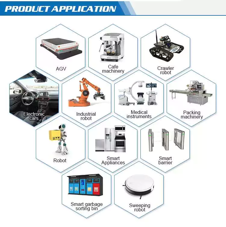
The gearboxes can be applied to numerous industrial location, these kinds of as Metallurgical, mines, lifting, transportation, petrochemical, building, textile, pharmaceutical, foodstuff, environmental, light-weight electric powered, plastic machine, paper, parking equipment and so on. Our specialized engineers can select design for you in accordance to your Request, and we also can supply our manufacturing facility catalogue for your reference.
Worm Equipment Speed Reducer/ gearbox
Specificatiion

Types
Rated Energy
Rated Ratio
Input Hole Dia.
Input Shaft Dia.
Output Gap Dia.
Output Shaft Dia.
RV571
.06KW~.12KW
five~60
Φ9
Φ9
Φ11
Φ11
RV030
.06KW~.25KW
5~eighty
Φ9(Φ11)
Φ9
Φ14
Φ14
RV040
.09KW~.55KW
five~100
Φ9(Φ11,Φ14)
Φ11
Φ18(Φ19)
Φ18
RV050
.12KW~1.5KW
5~a hundred
Φ11(Φ14,Φ19)
Φ14
Φ25(Φ24)
Φ25
RV063
.18KW~2.2KW
seven.5~a hundred
Φ14(Φ19,Φ24)
Φ19
Φ25(Φ28)
Φ25
RV075
.25KW~4.0KW
seven.5~one hundred
Φ14(Φ19,Φ24,Φ28)
Φ24
Φ28(Φ35)
Φ28
RV090
.37KW~4.0KW
seven.5~100
Φ19(Φ24,Φ28)
Φ24
Φ35(Φ38)
Φ35
RV110
.55KW~7.5KW
7.5~100
Φ19(Φ24,Φ28,Φ38)
Φ28
Φ42
Φ42
RV130
.75KW~7.5KW
seven.5~100
Φ24(Φ28,Φ38)
Φ30
Φ45
Φ45
RV150
two.2KW~15KW
7.5~100
Φ28(Φ38,Φ42)
Φ35
Φ50
Φ50

Firm Information

Packaging & Transport

FAQ
one. How to choose a gearbox which fulfills our need?
You can refer to our catalogue to choose the gearbox or we can help to select when you supply
the complex information of needed output torque, output speed and motor parameter and many others.

2. What information shall we give prior to positioning a purchase purchase?
a) Variety of the gearbox, ratio, input and output variety, enter flange, mounting placement, and motor informationetc.
b) Housing shade.
c) Buy quantity.
d) Other specific needs.

3. Can we acquire 1 computer of every single item for good quality tests?
Of course, we are glad to accept trial order for top quality testing

4. How extended is your shipping and delivery time?
Generally it is 5-ten days if the merchandise are in stock. or it is fifteen-twenty days if the items are not in stock.
Get in touch with Us

Choosing a Gearbox For Your Application

The gearbox is an essential part of bicycles. It is used for several purposes, including speed and force. A gearbox is used to achieve one or both of these goals, but there is always a trade-off. Increasing speed increases wheel speed and forces on the wheels. Similarly, increasing pedal force increases the force on the wheels. This makes it easier for cyclists to accelerate their bicycles. However, this compromise makes the gearbox less efficient than an ideal one.
gearbox

Dimensions

Gearboxes come in different sizes, so the size of your unit depends on the number of stages. Using a chart to determine how many stages are required will help you determine the dimensions of your unit. The ratios of individual stages are normally greater at the top and get smaller as you get closer to the last reduction. This information is important when choosing the right gearbox for your application. However, the dimensions of your gearbox do not have to be exact. Some manufacturers have guides that outline the required dimensions.
The service factor of a gearbox is a combination of the required reliability, the actual service condition, and the load that the gearbox will endure. It can range from 1.0 to 1.4. If the service factor of a gearbox is 1.0, it means that the unit has just enough capacity to meet your needs, but any extra requirements could cause the unit to fail or overheat. However, service factors of 1.4 are generally sufficient for most industrial applications, since they indicate that a gearbox can withstand 1.4 times its application requirement.
Different sizes also have different shapes. Some types are concentric, while others are parallel or at a right angle. The fourth type of gearbox is called shaft mount and is used when mounting the gearbox by foot is impossible. We will discuss the different mounting positions later. In the meantime, keep these dimensions in mind when choosing a gearbox for your application. If you have space constraints, a concentric gearbox is usually your best option.

Construction

The design and construction of a gearbox entails the integration of various components into a single structure. The components of a gearbox must have sufficient rigidity and adequate vibration damping properties. The design guidelines note the approximate values for the components and recommend the production method. Empirical formulas were used to determine the dimensions of the various components. It was found that these methods can simplify the design process. These methods are also used to calculate the angular and axial displacements of the components of the gearbox.
In this project, we used a 3D modeling software called SOLIDWORKS to create a 3-D model of a gear reducer. We used this software to simulate the structure of the gearbox, and it has powerful design automation tools. Although the gear reducer and housing are separate parts, we model them as a single body. To save time, we also removed the auxiliary elements, such as oil inlets and oil level indicators, from the 3D model.
Our method is based on parameter-optimized deep neural networks (DBNs). This model has both supervised and unsupervised learning capabilities, allowing it to be self-adaptive. This method is superior to traditional methods, which have poor self-adaptive feature extraction and shallow network generalization. Our algorithm is able to recognize faults in different states of the gearbox using its vibration signal. We have tested our model on two gearboxes.
With the help of advanced material science technologies, we can now manufacture the housing for the gearbox using high-quality steel and aluminium alloys. In addition, advanced telematics systems have increased the response time of manufacturers. These technologies are expected to create tremendous opportunities in the coming years and fuel the growth of the gearbox housing market. There are many different ways to construct a gearbox, and these techniques are highly customizable. In this study, we will consider the design and construction of various gearbox types, as well as their components.
gearbox

Working

A gearbox is a mechanical device that transmits power from one gear to another. The different types of gears are called planetary gears and are used in a variety of applications. Depending on the type of gearbox, it may be concentric, parallel, or at a right angle. The fourth type of gearbox is a shaft mount. The shaft mount type is used in applications that cannot be mounted by foot. The various mounting positions will be discussed later.
Many design guidelines recommend a service factor of 1.0, which needs to be adjusted based on actual service conditions. This factor is the combined measure of external load, required reliability, and overall gearbox life. In general, published service factors are the minimum requirements for a particular application, but a higher value is necessary for severe loading. This calculation is also recommended for high-speed gearboxes. However, the service factor should not be a sole determining factor in the selection process.
The second gear of a pair of gears has more teeth than the first gear. It also turns slower, but with greater torque. The second gear always turns in the opposite direction. The animation demonstrates this change in direction. A gearbox can also have more than one pair of gears, and a first gear may be used for the reverse. When a gear is shifted from one position to another, the second gear is engaged and the first gear is engaged again.
Another term used to describe a gearbox is “gear box.” This term is an interchangeable term for different mechanical units containing gears. Gearboxes are commonly used to alter speed and torque in various applications. Hence, understanding the gearbox and its parts is essential to maintaining your car’s performance. If you want to extend the life of your vehicle, be sure to check the gearbox’s efficiency. The better its functioning, the less likely it is to fail.

Advantages

Automatic transmission boxes are almost identical to mechanical transmission boxes, but they also have an electronic component that determines the comfort of the driver. Automatic transmission boxes use special blocks to manage shifts effectively and take into account information from other systems, as well as the driver’s input. This ensures accuracy and positioning. The following are a few gearbox advantages:
A gearbox creates a small amount of drag when pedaling, but this drag is offset by the increased effort to climb. The external derailleur system is more efficient when adjusted for friction, but it does not create as little drag in dry conditions. The internal gearbox allows engineers to tune the shifting system to minimize braking issues, pedal kickback, and chain growth. As a result, an internal gearbox is a great choice for bikes with high-performance components.
Helical gearboxes offer some advantages, including a low noise level and lower vibration. They are also highly durable and reliable. They can be extended in modular fashion, which makes them more expensive. Gearboxes are best for applications involving heavy loads. Alternatively, you can opt for a gearbox with multiple teeth. A helical gearbox is more durable and robust, but it is also more expensive. However, the benefits far outweigh the disadvantages.
A gearbox with a manual transmission is often more energy-efficient than one with an automatic transmission. Moreover, these cars typically have lower fuel consumption and higher emissions than their automatic counterparts. In addition, the driver does not have to worry about the brakes wearing out quickly. Another advantage of a manual transmission is its affordability. A manual transmission is often available at a lower cost than its automatic counterpart, and repairs and interventions are easier and less costly. And if you have a mechanical problem with the gearbox, you can control the fuel consumption of your vehicle with appropriate driving habits.
gearbox

Application

While choosing a gearbox for a specific application, the customer should consider the load on the output shaft. High impact loads will wear out gear teeth and shaft bearings, requiring higher service factors. Other factors to consider are the size and style of the output shaft and the environment. Detailed information on these factors will help the customer choose the best gearbox. Several sizing programs are available to determine the most appropriate gearbox for a specific application.
The sizing of a gearbox depends on its input speed, torque, and the motor shaft diameter. The input speed must not exceed the required gearbox’s rating, as high speeds can cause premature seal wear. A low-backlash gearbox may be sufficient for a particular application. Using an output mechanism of the correct size may help increase the input speed. However, this is not recommended for all applications. To choose the right gearbox, check the manufacturer’s warranty and contact customer service representatives.
Different gearboxes have different strengths and weaknesses. A standard gearbox should be durable and flexible, but it must also be able to transfer torque efficiently. There are various types of gears, including open gearing, helical gears, and spur gears. Some of the types of gears can be used to power large industrial machines. For example, the most popular type of gearbox is the planetary drive gearbox. These are used in material handling equipment, conveyor systems, power plants, plastics, and mining. Gearboxes can be used for high-speed applications, such as conveyors, crushers, and moving monorail systems.
Service factors determine the life of a gearbox. Often, manufacturers recommend a service factor of 1.0. However, the actual value may be higher or lower than that. It is often useful to consider the service factor when choosing a gearbox for a particular application. A service factor of 1.4 means that the gearbox can handle 1.4 times the load required. For example, a 1,000-inch-pound gearbox would need a 1,400-inch-pound gearbox. Service factors can be adjusted to suit different applications and conditions.

China Standard NMRV +NRV small Worm Gear Reducer Worm Gearboxes     brushless dc motor worm gearboxChina Standard NMRV +NRV small Worm Gear Reducer Worm Gearboxes     brushless dc motor worm gearbox
editor by czh

China Custom BLDC DC Brushless Gear Motor with Gear Circular Shaft Ear Flat Hollow Screw Hole Through Hole Right Angle Hollow Solid Worm Gearbox with high quality

Product Description

DC Blushless Gear Motor
G 2 BLD(P) 40 220 GN 30S
Enterprise Code Mounting Flange Motor Type Output Power Voltage Shape of Motor Shaft Motor Speed
G – GPG 2-60mm
3-70mm
4-80mm
5-90mm
6-100mm
BLD – Brushless motor
            with square gearbox

BLDP – Brushless motor
              with planetary gearbox 

10 – 10W
15 – 15W
25 – 25W
40 – 40W
60 – 60W
90 – 90W
200 – 200W
400 – 400W
24 – DC24V
36 – DC36V
48 – DC48V
110 – DC110V
220 – DC220V
GN – General Helival Gear
GU – Reinforced Helival Gear
A1 – Milling Keyway
A – Flat type
15S – 1500RPM
18S – 1800RPM
25S – 2500RPM
30S – 3000RPM
Gearbox
2 GN 50 RT
Model & Dimension Gear Type Reduction Ratio Bearing Type
2: 60mm
4: 80mm
5: 90mm
6: 104mm
GN: General Helical Gear
GU: Reinforced Helical Gear
50: Reduction Ratio 1:50
10X Denotes The Mid-gearbox Ration 1:10
RT – Right Angle
RC – Right-Angle Hollow
5 GFS 100 K 20
Model & Dimension Gear Type Reduction Ratio Bearing Type Out-shaft Diameter
2: 60mm
4: 80mm
5: 90mm
6: 100mm
Flat Boxes
Hollow Output
100
The reduction ratio of reducer can be said speed ratio range, for example, 50-75, may also be a separate ratio,
for example 100
K: standard rolling bearing
H: sliding bearing
L: axle type
Z: hybrid bearings
20: Φ20mm

Motor Performance Parameters
Model Voltage No-load Current No-load Speed Rated Power Rated Current Rated Speed Rated Torque Grade Protection
V A RPM W A RPM N.m IP
G2BLD25-24GN-30S 24 MAX 0.4 3200 25 1.3 3000 0.08 44
G2BLD25-36GN-30S 36 MAX 0.3 0.9
G2BLD25-48GN-30S 48 MAX 0.2 0.7
Motor Model
Type Pinion Shaft Round Shaft
Lead Wire G2BLD200-24GN-30S G2BLD200-24A1-30S
G2BLD200-36GN-30S G2BLD200-36A1-30S
G2BLD200-48GN-30S G2BLD200-48A1-30S
Parallel Shaft Gearhead (Sold Separately)
Gearhead Type Gearhead Model Gear Ratio
Long Life, Low Noise 2GN/GU _ RC/RT 3, 3.6, 5, 6, 7.5, 9, 12.5, 15, 18,
25, 30, 36, 50, 60, 75, 90,
100, 120, 150, 180, 200
2GN10XK ( Decimal Gearhead ) 
Allowance Torque Unit: Upside (N-m) / Belowside (kgf.cm)
Gear Ratio 3 3.6 5 6 7.5 9 12.5 15 18 25 30 36 50 60 75 90 100 120 150 180 200
r/min Output Shaft Speed 1000 830 600 500 400 330 240 200 166 120 100 83 60 50 40 33 30 25 20 16 15
GU Allowance Torque N·m  0.19 0.23 0.32 0.38 0.48 0.58 0.81 0.87 1.16 1.44 1.73 2.07 2.52 3 3 3 3 3 3 3 3

FAQ
Q: How about your company?
A: We are a gear motor factory established in 1995 and located in HangZhou city of china. 
     We have more than 1200 workers. Our main product is AC micro gear motor 6W to 250W, 
     AC small gear motor 100W to 3700W, brush DC motor 10W to 400W, brushless motor10W to 750W,
     drum motor 60W to 3700W, planetary gearbox,and worm gearbox,etc.

Q: How about your quality control?
A: From raw material to finished products, we have strict and complete IPQC. 
     And the advanced test-ing machine can assure of qualified products delivered.

Q: How to choose a suitable motor?
A: If you have gear motor pictures or drawings to show us, 
    or you tell us detailed specs like volt-age, speed, torque, motor size, the working model of the motor, needed lifetime and noise level, etc. 
    please do not hesitate to let us know, then we can suggest a suitable motor per your request.

Q: Can you make the gear motor with customizing specifications?
A: Yes, we can customize per your request for the voltage, speed, torque, and shaft size and shape. 
     if you need additional wires or cables soldered on the terminal or need to add connectors, or capacitors, or EMC we can make it too.

Q: What’s your lead time?
A: Usually our regular standard product will need 10-15days, a bit longer for customized products. 
     But we are very flexible on the lead time, it will depend on the specific orders.

Q: What is your MOQ?
A: If delivered by sea, the minimum order is 100 pieces, if deliver by express, there is no limit.

Q: Do you have the item in stock?
A: l am sorry we do not have the item in stock, All products are made with orders.

Q: How to contact us?
A: You can send us an inquiry.


Lead Screws and Clamp Style Collars

If you have a lead screw, you’re probably interested in learning about the Acme thread on this type of shaft. You might also be interested in finding out about the Clamp style collars and Ball screw nut. But before you buy a new screw, make sure you understand what the terminology means. Here are some examples of screw shafts:

Acme thread

The standard ACME thread on a screw shaft is made of a metal that is resistant to corrosion and wear. It is used in a variety of applications. An Acme thread is available in a variety of sizes and styles. General purpose Acme threads are not designed to handle external radial loads and are supported by a shaft bearing and linear guide. Their design is intended to minimize the risk of flank wedging, which can cause friction forces and wear. The Centralizing Acme thread standard caters to applications without radial support and allows the thread to come into contact before its flanks are exposed to radial loads.
The ACME thread was first developed in 1894 for machine tools. While the acme lead screw is still the most popular screw in the US, European machines use the Trapezoidal Thread (Metric Acme). The acme thread is a stronger and more resilient alternative to square threads. It is also easier to cut than square threads and can be cut by using a single-point threading die.
Similarly to the internal threads, the metric versions of Acme are similar to their American counterparts. The only difference is that the metric threads are generally wider and are used more frequently in industrial settings. However, the metric-based screw threads are more common than their American counterparts worldwide. In addition, the Acme thread on screw shafts is used most often on external gears. But there is still a small minority of screw shafts that are made with a metric thread.
ACME screws provide a variety of advantages to users, including self-lubrication and reduced wear and tear. They are also ideal for vertical applications, where a reduced frictional force is required. In addition, ACME screws are highly resistant to back-drive and minimize the risk of backlash. Furthermore, they can be easily checked with readily available thread gauges. So, if you’re looking for a quality ACME screw for your next industrial project, look no further than ACME.
screwshaft

Lead screw coatings

The properties of lead screw materials affect their efficiency. These materials have high anti-corrosion, thermal resistance, and self-lubrication properties, which eliminates the need for lubrication. These coating materials include polytetrafluoroethylene (PFE), polyether ether ketone (PEK), and Vespel. Other desirable properties include high tensile strength, corrosion resistance, and rigidity.
The most common materials for lead screws are carbon steel, stainless steel, and aluminum. Lead screw coatings can be PTFE-based to withstand harsh environments and remove oil and grease. In addition to preventing corrosion, lead screw coatings improve the life of polymer parts. Lead screw assembly manufacturers offer a variety of customization options for their lead screw, including custom-molded nuts, thread forms, and nut bodies.
Lead screws are typically measured in rpm, or revolutions per minute. The PV curve represents the inverse relationship between contact surface pressure and sliding velocity. This value is affected by the material used in the construction of the screw, lubrication conditions, and end fixity. The critical speed of lead screws is determined by their length and minor diameter. End fixity refers to the support for the screw and affects its rigidity and critical speed.
The primary purpose of lead screws is to enable smooth movement. To achieve this, lead screws are usually preloaded with axial load, enabling consistent contact between a screw’s filets and nuts. Lead screws are often used in linear motion control systems and feature a large area of sliding contact between male and female threads. Lead screws can be manually operated or mortised and are available in a variety of sizes and materials. The materials used for lead screws include stainless steel and bronze, which are often protected by a PTFE type coating.
These screws are made of various materials, including stainless steel, bronze, and various plastics. They are also made to meet specific requirements for environmental conditions. In addition to lead screws, they can be made of stainless steel, aluminum, and carbon steel. Surface coatings can improve the screw’s corrosion resistance, while making it more wear resistant in tough environments. A screw that is coated with PTFE will maintain its anti-corrosion properties even in tough environments.
screwshaft

Clamp style collars

The screw shaft clamp style collar is a basic machine component, which is attached to the shaft via multiple screws. These collars act as mechanical stops, load bearing faces, or load transfer points. Their simple design makes them easy to install. This article will discuss the pros and cons of this style of collar. Let’s look at what you need to know before choosing a screw shaft clamp style collar. Here are some things to keep in mind.
Clamp-style shaft collars are a versatile mounting option for shafts. They have a recessed screw that fully engages the thread for secure locking. Screw shaft clamp collars come in different styles and can be used in both drive and power transmission applications. Listed below are the main differences between these 2 styles of collars. They are compatible with all types of shafts and are able to handle axial loads of up to 5500 pounds.
Clamp-style shaft collars are designed to prevent the screw from accidentally damaging the shaft when tightened. They can be tightened with a set screw to counteract the initial clamping force and prevent the shaft from coming loose. However, when tightening the screw, you should use a torque wrench. Using a set screw to tighten a screw shaft collar can cause it to warp and reduce the surface area that contacts the shaft.
Another key advantage to Clamp-style shaft collars is that they are easy to install. Clamp-style collars are available in one-piece and two-piece designs. These collars lock around the shaft and are easy to remove and install. They are ideal for virtually any shaft and can be installed without removing any components. This type of collar is also recommended for those who work on machines with sensitive components. However, be aware that the higher the OD, the more difficult it is to install and remove the collar.
Screw shaft clamp style collars are usually one-piece. A two-piece collar is easier to install than a one-piece one. The two-piece collars provide a more effective clamping force, as they use the full seating torque. Two-piece collars have the added benefit of being easy to install because they require no tools to install. You can disassemble one-piece collars before installing a two-piece collar.
screwshaft

Ball screw nut

The proper installation of a ball screw nut requires that the nut be installed on the center of the screw shaft. The return tubes of the ball nut must be oriented upward so that the ball nut will not overtravel. The adjusting nut must be tightened against a spacer or spring washer, then the nut is placed on the screw shaft. The nut should be rotated several times in both directions to ensure that it is centered.
Ball screw nuts are typically manufactured with a wide range of preloads. Large preloads are used to increase the rigidity of a ball screw assembly and prevent backlash, the lost motion caused by a clearance between the ball and nut. Using a large amount of preload can lead to excessive heat generation. The most common preload for ball screw nuts is 1 to 3%. This is usually more than enough to prevent backlash, but a higher preload will increase torque requirements.
The diameter of a ball screw is measured from its center, called the ball circle diameter. This diameter represents the distance a ball will travel during 1 rotation of the screw shaft. A smaller diameter means that there are fewer balls to carry the load. Larger leads mean longer travels per revolution and higher speeds. However, this type of screw cannot carry a greater load capacity. Increasing the length of the ball nut is not practical, due to manufacturing constraints.
The most important component of a ball screw is a ball bearing. This prevents excessive friction between the ball and the nut, which is common in lead-screw and nut combinations. Some ball screws feature preloaded balls, which avoid “wiggle” between the nut and the ball. This is particularly desirable in applications with rapidly changing loads. When this is not possible, the ball screw will experience significant backlash.
A ball screw nut can be either single or multiple circuits. Single or multiple-circuit ball nuts can be configured with 1 or 2 independent closed paths. Multi-circuit ball nuts have 2 or more circuits, making them more suitable for heavier loads. Depending on the application, a ball screw nut can be used for small clearance assemblies and compact sizes. In some cases, end caps and deflectors may be used to feed the balls back to their original position.

China Custom BLDC DC Brushless Gear Motor with Gear Circular Shaft Ear Flat Hollow Screw Hole Through Hole Right Angle Hollow Solid Worm Gearbox   with high qualityChina Custom BLDC DC Brushless Gear Motor with Gear Circular Shaft Ear Flat Hollow Screw Hole Through Hole Right Angle Hollow Solid Worm Gearbox   with high quality