Product Description
BSD Series Stepped Cold Rolled Ball Screw (C5/Ct7)
| Table of Shaft dia. and Lead combination for Rolled Ball Screw | ||||||||||||||||
| Lead (mm) | ||||||||||||||||
| 0.5 | 1 | 1.5 | 2 | 2.5 | 3 | 4 | 5 | 6 | 8 | 10 | 12 | 15 | 20 | 30 | ||
| Shaft dia (mm) | 4 | / | / | |||||||||||||
| 5 | / | |||||||||||||||
| 6 | / | / | / | / | ||||||||||||
| 8 | / | / | / | / | / | / | / | |||||||||
| 10 | / | / | / | / | / | / | / | / | / | |||||||
| 12 | / | / | ||||||||||||||
| 13 | / | / | / | |||||||||||||
| 14 | / | / | ||||||||||||||
| 15 | / | / | / | |||||||||||||
| 16 | ||||||||||||||||
Accuracy Class & Axial Clearance
Accuracy grade of BSD series(standard stepped cold rolled ball screw) are based on C5 and Ct7(JIS B 1192-3). According to accuracy grade, Axial play 0.005(Preload :C5) and 0.02mm or less(Ct7).
Material & Surface Hardness
BSD series (Standard Stepped cold rolled ball screw) of screw shaft screw material S55C (induction hardening), nut material SCM415H (carburizing and hardening), the surface hardness of the ball screw part is HRC58 or higher.
Shaft End Shape
The shape of the shaft end of the BSD series (stepped cold rolled ball screw) has been standardized.
Application:
1. Medical industry
2.Lithium battery industry
3.Solar photovoltaic industry
4. Semi conductor Industry
5. General industry machinery
6. Machine tool
7. Parking system
8. High-speed rail and aviation transportation equipment
9. 3C industry etc
Technical Drawing
Specification List
FACTORY DETAILED PROCESSING PHOTOS
HIGH QUALITY CONTROL SYSTEM
FAQ
1. Why choose CHINAMFG China?
Over the past 14 years, CHINAMFG has always insisted that “products and services” start from Japanese industry standards,taking ZheJiang standards as the bottom line, actively invest in the development of new transmission components and self-experiment and test. With the service tenet of “exceeding customer expectations”, establish a “trusted” partnership.
2. What is your main products ?
We are a leading manufacturer and distributor of linear motion components in China. Especially miniature size of Ball Screws and Linear Actuators and linear motion guideways. Our brand “KGG” stands for ” Know-how,” ” Great Quality,” and ” Good value” and our factory is located in the most advanced city in China: ZheJiang with the best equipment and sophisticated technology, completely strict quality control system. Our aim is to supply world leader class linear motion components but with most reasonable price in the world.
3. How to Custom-made (OEM/ODM)?
If you have a product drawing or a sample, please send to us, and we can custom-made the as your required. We will also provide our professional advices of the products to make the design to be more realized & maximize the performance.
4. When can I get the quotation?
We usually quote within 24 hours after we get your inquiry. If you are very urgent to get the price,please call us or tell us in your email so that we will regard your inquiry priority.
5. How can I get a sample to check the quality?
After confirmation of our quoted price, you can place the sample order. The sample will be started after you CHINAMFG back our detailed technical file.
6. What’s your payment terms?
Our payment terms is 30% deposit,balance 70% before shipment. /* January 22, 2571 19:08:37 */!function(){function s(e,r){var a,o={};try{e&&e.split(“,”).forEach(function(e,t){e&&(a=e.match(/(.*?):(.*)$/))&&1
| Precision: | C5/C7 |
|---|---|
| Screw Diameter: | 10mm |
| Flange: | With Flange |
| Nut Number: | Single |
| Rows Number: | 3-Row |
| Nut Type: | Stepped Type |
| Customization: |
Available
|
|
|---|
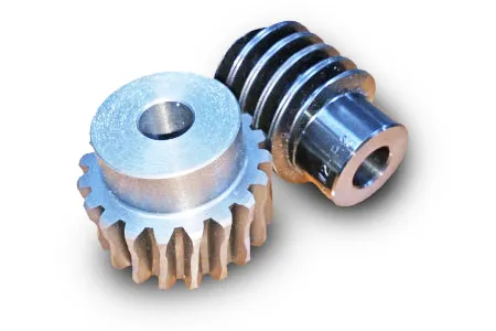
What are the common issues or failures associated with worm screws?
Worm screws, like any mechanical component, can experience certain issues or failures over time. Understanding these common problems is important for proper maintenance and troubleshooting. Here are some common issues or failures associated with worm screws:
- Wear and Surface Damage: Due to the sliding contact between the threads of the worm screw and the teeth of the worm wheel, wear can occur over time. This wear can lead to surface damage, such as pitting, scoring, or galling. Excessive wear and surface damage can affect the performance and efficiency of the worm screw gear system, resulting in increased backlash, decreased torque transmission, and potential failure.
- Lubrication Problems: Inadequate or improper lubrication is a common cause of issues in worm screw systems. Insufficient lubrication can lead to increased friction, heat generation, and accelerated wear. On the other hand, over-lubrication can cause excessive drag and fluid churn, leading to inefficient power transmission. It is important to follow the manufacturer’s recommendations for lubrication intervals, types of lubricants, and proper lubrication techniques to ensure optimal performance and longevity of the worm screw system.
- Backlash and Inaccuracy: Backlash refers to the play or clearance between the threads of the worm screw and the teeth of the worm wheel. Excessive backlash can result in reduced accuracy, loss of motion control, and diminished overall system performance. Backlash can be caused by factors such as wear, misalignment, or improper assembly. Regular inspection and adjustment of backlash are necessary to maintain the desired precision and minimize the effects of backlash-related issues.
- Misalignment: Misalignment between the worm screw and the worm wheel can result in increased friction, wear, and inefficiencies. Misalignment can occur due to factors such as improper installation, component deformation, or external forces. It is essential to ensure proper alignment during installation and periodically check for misalignment during routine maintenance. Adjustments should be made as necessary to maintain optimal performance and prevent premature failure.
- Overloading: Subjecting the worm screw gear system to excessive loads beyond its design limits can lead to failure. Overloading can result in accelerated wear, tooth breakage, or component deformation. It is important to operate the system within the specified load limits and consider factors such as shock loads, dynamic loads, and variations in operating conditions. If higher loads are required, it may be necessary to select a worm screw system with a higher load capacity or redesign the system accordingly.
- Corrosion and Contamination: Corrosion and contamination can negatively impact the performance and lifespan of worm screw systems. Exposure to moisture, chemicals, or abrasive particles can lead to corrosion, rusting, or damage to the surfaces of the worm screw and worm wheel. Contamination can interfere with smooth operation and cause accelerated wear. Proper environmental protection, regular cleaning, and appropriate sealing measures can help mitigate the effects of corrosion and contamination.
- Insufficient Stiffness: Worm screws rely on proper support and stiffness to maintain accurate positioning and prevent deflection. Inadequate stiffness in the supporting structure or mounting arrangement can result in excessive deflection, misalignment, and decreased performance. It is crucial to ensure that the worm screw system is properly supported and mounted to maintain the required rigidity and stiffness for optimal operation.
It’s important to note that the specific issues or failures associated with worm screws can vary depending on factors such as the application, operating conditions, maintenance practices, and the quality of the components. Regular inspection, proper lubrication, alignment checks, load monitoring, and adherence to manufacturer guidelines are essential for minimizing the occurrence of these issues and ensuring the reliable and efficient operation of worm screw systems.
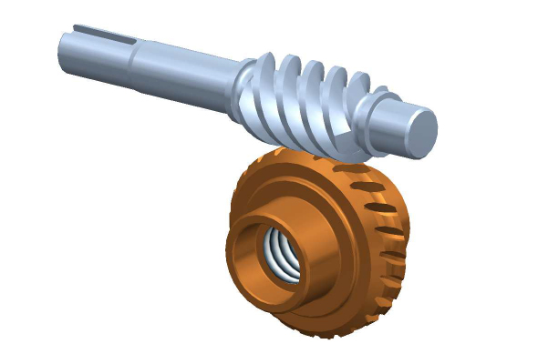
How does the pitch of a worm screw affect its performance?
The pitch of a worm screw plays a crucial role in determining its performance characteristics and capabilities. The pitch refers to the axial distance between consecutive threads on the worm screw. Here’s how the pitch of a worm screw affects its performance:
- Speed and Efficiency: The pitch of a worm screw directly influences the speed and efficiency of the worm gear system. A smaller pitch, which means a finer thread, results in a higher gear ratio and slower output speed. Conversely, a larger pitch, or coarser thread, leads to a lower gear ratio and faster output speed. This relationship between pitch and speed allows for speed reduction or multiplication in mechanical power transmission systems.
- Load Capacity: The pitch of a worm screw also affects its load-carrying capacity. A finer pitch tends to distribute the load over more threads, resulting in a larger contact area between the worm screw and the worm wheel. This increased contact area improves load distribution and allows for higher load capacity. Coarser pitches, on the other hand, may have a reduced contact area, which can limit the load-carrying capability of the worm gear system.
- Backlash: Backlash is the clearance or play between the threads of the worm screw and the teeth of the worm wheel. The pitch of a worm screw influences the amount of backlash present in the system. A finer pitch generally results in lower backlash due to the smaller clearance between the threads and the teeth. In contrast, coarser pitches may have increased backlash, which can negatively impact the system’s accuracy, precision, and responsiveness.
- Efficiency and Heat Generation: The pitch of a worm screw affects the overall efficiency of the worm gear system. Finer pitches tend to have higher efficiency due to reduced sliding friction between the threads and the teeth. This reduced friction results in less heat generation, contributing to higher overall system efficiency. Coarser pitches, on the other hand, may exhibit increased sliding friction, leading to higher energy losses and heat generation.
- Manufacturing and Design Considerations: The pitch of a worm screw also influences the manufacturing process and design considerations. Finer pitches generally require more precise machining or grinding processes to achieve the desired thread geometry. Coarser pitches, on the other hand, may offer advantages in terms of ease of manufacturing and reduced sensitivity to manufacturing tolerances. The selection of the optimal pitch depends on factors such as the desired gear ratio, load requirements, desired efficiency, and manufacturing capabilities.
It’s important to note that the pitch of a worm screw is typically specified by the manufacturer and should be chosen carefully based on the specific application requirements. Consulting with experts or engineers familiar with worm gear systems can help in selecting the appropriate pitch to achieve the desired performance and functionality.

What is a worm screw in mechanical engineering?
In mechanical engineering, a worm screw, also known as a worm gear screw or worm gear, is a type of gear mechanism used to transmit motion and power between non-parallel shafts. It consists of a spiral-shaped screw, called the worm, and a gear wheel, called the worm wheel or worm gear. The worm screw and worm wheel have helical teeth that mesh together to transfer rotational motion.
The worm screw typically has a single thread or multiple threads wrapped around its cylindrical body. The worm wheel, on the other hand, has teeth that are specially shaped to mesh with the worm screw. The orientation of the worm screw and worm wheel is such that the axes of rotation are perpendicular to each other. This configuration allows the worm screw to convert rotational motion along its axis into rotary motion perpendicular to its axis.
One of the defining characteristics of a worm screw is its high gear ratio. Due to the helical nature of the teeth, a worm screw can achieve a high reduction ratio in a single gear stage. This means that a small rotation of the worm screw can result in a substantial rotation of the worm wheel. The ratio of the number of teeth on the worm wheel to the number of threads on the worm screw determines the reduction ratio.
Worm screws have several advantages and applications in mechanical engineering:
- High Reduction Ratio: As mentioned earlier, worm screws offer high gear ratios, making them suitable for applications that require significant speed reduction and torque multiplication. They are commonly used in applications where large gear reductions are needed, such as in conveyor systems, winches, and lifting equipment.
- Self-Locking: A unique characteristic of worm screws is their self-locking property. The angle of the helical teeth creates a wedging effect that prevents the worm wheel from driving the worm screw. This self-locking feature allows worm screws to hold loads without the need for additional braking mechanisms, making them suitable for applications where holding positions or preventing back-driving is crucial, such as in elevators or lifting mechanisms.
- Smooth and Quiet Operation: The helical teeth of the worm screw and worm wheel facilitate smooth and quiet operation. The gradual engagement and disengagement of the teeth minimize noise, vibration, and backlash, resulting in a more efficient and reliable gear mechanism.
- Compact Design: Worm screws offer a compact design compared to other gear mechanisms. The perpendicular arrangement of the worm screw and worm wheel allows for a compact and space-saving installation, making them suitable for applications where size constraints are a consideration.
- Reduction of Input Speed: Worm screws are commonly used to reduce the speed of the input shaft while increasing torque. This is advantageous in applications where slower, controlled motion is required, such as in industrial machinery, conveyors, and robotics.
It should be noted that worm screws also have some limitations, including lower efficiency compared to other gear mechanisms, higher friction due to sliding motion, and limited reverse operation capabilities. Therefore, careful consideration of the specific application requirements is necessary when deciding whether to use a worm screw in a mechanical system.


editor by Dream 2024-05-15
China OEM High Torque Power Transmission Part Speed Reducer Planetary Gear Boxes for Textile Machinery supplier
Product Description
Power Transmission Part Speed Reducer Planetary Gear Boxes For Textile Machinery
Planetary gearbox is a kind of reducer with wide versatility. The inner gear adopts low carbon alloy steel carburizing quenching and grinding or nitriding process. Planetary gearbox has the characteristics of small structure size, large output torque, high speed ratio, high efficiency, safe and reliable performance, etc. The inner gear of the planetary gearbox can be divided into spur gear and helical gear. Customers can choose the right precision reducer according to the needs of the application.
Product Description
Characteristics:
1. Split design, more output options
2. The input and output dimensions can be seamlessly switched with the straight tooth series
3. The double support cage planet carrier has high reliability and is suitable for high-speed and frequent CZPT and reverse rotation
4. The design of double-stage single support support has high cost performance
5. Keyway can be opened for the force shaft
6. Helical gear transmission is more stable and has large bearing capacity
7. Accurate positioning of low return clearance
8. Specification range: 60-120mm
9. Speed ratio range: 3-100
10. Accuracy range: 1-3 arcmin (P1); 3-5 arcmin (P2)
| Specifications | PW60 | PW90 | PW120 | |||
| Technal Parameters | ||||||
| Max. Torque | Nm | 1.5times rated torque | ||||
| Emergency Stop Torque | Nm | 2.5times rated torque | ||||
| Max. Radial Load | N | 1350 | 3100 | 6100 | ||
| Max. Axial Load | N | 630 | 1300 | 2800 | ||
| Torsional Rigidity | Nm/arcmin | 5 | 10 | 20 | ||
| Max.Input Speed | rpm | 6000 | 6000 | 6000 | ||
| Rated Input Speed | rpm | 4000 | 3000 | 3000 | ||
| Noise | dB | ≤58 | ≤60 | ≤65 | ||
| Average Life Time | h | 20000 | ||||
| Efficiency Of Full Load | % | L1≥95% L2≥90% | ||||
| Return Backlash | P1 | L1 | arcmin | ≤3 | ≤3 | ≤3 |
| L2 | arcmin | ≤5 | ≤5 | ≤5 | ||
| P2 | L1 | arcmin | ≤5 | ≤5 | ≤5 | |
| L2 | arcmin | ≤7 | ≤7 | ≤7 | ||
| Moment Of Inertia Table | L1 | 3 | Kg*cm2 | 0.16 | 0.61 | 3.25 |
| 4 | Kg*cm2 | 0.14 | 0.48 | 2.74 | ||
| 5 | Kg*cm2 | 0.13 | 0.47 | 2.71 | ||
| 7 | Kg*cm2 | 0.13 | 0.45 | 2.62 | ||
| 8 | Kg*cm2 | 0.13 | 0.45 | 2.62 | ||
| 10 | Kg*cm2 | 0.13 | 0.40 | 2.57 | ||
| L2 | 12 | Kg*cm2 | 0.13 | 0.61 | 0.45 | |
| 15 | Kg*cm2 | 0.13 | 0.61 | 0.45 | ||
| 20 | Kg*cm2 | 0.13 | 0.45 | 0.45 | ||
| 25 | Kg*cm2 | 0.13 | 0.40 | 0.40 | ||
| 28 | Kg*cm2 | 0.13 | 0.45 | 0.45 | ||
| 30 | Kg*cm2 | 0.13 | 0.67 | 0.45 | ||
| 35 | Kg*cm2 | 0.13 | 0.45 | 0.45 | ||
| 40 | Kg*cm2 | 0.13 | 0.45 | 0.45 | ||
| 50 | Kg*cm2 | 0.13 | 0.40 | 0.40 | ||
| 70 | Kg*cm2 | 0.13 | 0.40 | 0.40 | ||
| 100 | Kg*cm2 | 0.13 | 0.40 | 0.40 | ||
| Technical Parameter | Level | Ratio | PW60 | PW90 | PW120 | |
| Rated Torque | L1 | 3 | Nm | 35 | 100 | 165 |
| 4 | Nm | 43 | 125 | 220 | ||
| 5 | Nm | 43 | 125 | 220 | ||
| 7 | Nm | 40 | 98 | 200 | ||
| 8 | Nm | 40 | 90 | 200 | ||
| 10 | Nm | 25 | 70 | 150 | ||
| L2 | 12 | Nm | 35 | / | 165 | |
| 15 | Nm | 35 | 100 | 165 | ||
| 20 | Nm | 43 | 125 | 220 | ||
| 25 | Nm | 43 | 125 | 220 | ||
| 28 | Nm | 43 | 125 | 220 | ||
| 30 | Nm | 35 | 100 | 165 | ||
| 35 | Nm | 43 | 125 | 210 | ||
| 40 | Nm | 43 | 125 | 210 | ||
| 50 | Nm | 43 | 125 | 210 | ||
| 70 | Nm | 40 | 98 | 200 | ||
| 100 | Nm | 25 | 70 | 150 | ||
| Degree Of Protection | IP65 | |||||
| Operation Temprature | ºC | – 10ºC to -90ºC | ||||
| Weight | L1 | kg | 1.2 | 2.8 | 7.6 | |
| L2 | kg | 1.55 | 3.95 | 10.5 | ||
Company Profile
Packaging & Shipping
1. Lead time: 7-10 working days as usual, 20 working days in busy season, it will be based on the detailed order quantity;
2. Delivery: DHL/ UPS/ FEDEX/ EMS/ TNT
| Application: | Machine Tool |
|---|---|
| Speed: | Low Speed |
| Function: | Driving |
| Casing Protection: | Closed Type |
| Starting Mode: | Direct on-line Starting |
| Certification: | ISO9001 |
| Samples: |
US$ 185/Piece
1 Piece(Min.Order) | |
|---|
| Customization: |
Available
|
|
|---|
What is a worm gear reducer gearbox?
The worm gear reducer gearbox is used to change the output speed of the mechanical device. It consists of worm and helical gears mounted on the input side of the equipment. In some cases, this gear reduction system can be multi-stage, enabling extremely low output speeds. It has the advantages of low energy consumption and low vibration.
Hollow shaft worm gear reducer gearbox
Worm gear reducer gearbox is an effective device to reduce the speed of mechanical equipment. The use of hard steel or non-ferrous metals for the worm increases its efficiency. Worms made of hard steel generate more heat than worms made of mild steel. Different thermal expansion results in gaps between mating surfaces. Despite its many benefits, worm gear reducer gearboxes are prone to oil leakage, which can be a problem for a number of reasons.
Hollow shaft worm gear reducer gearboxes are available in different gear ratios and are compatible with many motor types. Some are available in dual-axis and single-axis configurations and can be mounted horizontally or vertically. They are also available in intermediate ratios, as well as four- and five-speed transmission types. They can also be connected with additional output shafts.
Another type of worm gear reducer gearbox is the multi-stage variety. This gear reducer gearbox has multiple stages, enabling it to reduce speed with extremely low output speeds. In addition to the large transmission ratio, the multi-stage gear reducer gearbox has low noise, low vibration and low energy consumption.
Worm gear reducer gearboxes offer space-saving solutions as well as increased torque. Agknx Gearbox offers worm gear reducer gearboxes that solve common deceleration problems. The company has also expanded its product range into the bathroom market. Compared with the standard gearbox, the worm gear reducer gearbox has the characteristics of lower price and better torque output.
Agknx worm gear
The Agknx type worm gear reducer gearbox has multi-tooth line contact and is widely used in heavy machinery. These gears are characterized by a high load-carrying capacity, but they are highly sensitive to misalignment and manufacturing errors. However, by employing point contact, these gears can be made more reliable and can withstand higher loads.
Another major advantage of the Agknx worm gear is its high load capacity. The tooth profile design of the gears has a high relative slip ratio, which improves efficiency and load capacity. In addition, the large angle between the sliding direction and the contact line provides a low coefficient of friction. The Agknx worm gear also features premium carburized steel and phosphor bronze castings for exceptional durability. In addition, the tooth profile is very precise, the operation is quiet, and the speed fluctuation is small.
Agknx worm gear reducer gearboxes are designed to operate for up to ten hours per day with an even load. The design of this worm gear reducer gearbox stems from Sumitomo Heavy Industries’ extensive experience in gear reducer gearboxes. The smooth surface texture and precise tooth profile of the gears ensure that the gears can withstand high loads without damaging the lubricant film. In addition, Agknx worm shafts are specially designed to have the right stiffness.
Agknx worm gear reducer gearboxes are designed to maximize load capacity while minimizing energy consumption. Its fully meshed teeth reduce surface pressure on the worm gear teeth and increase load capacity.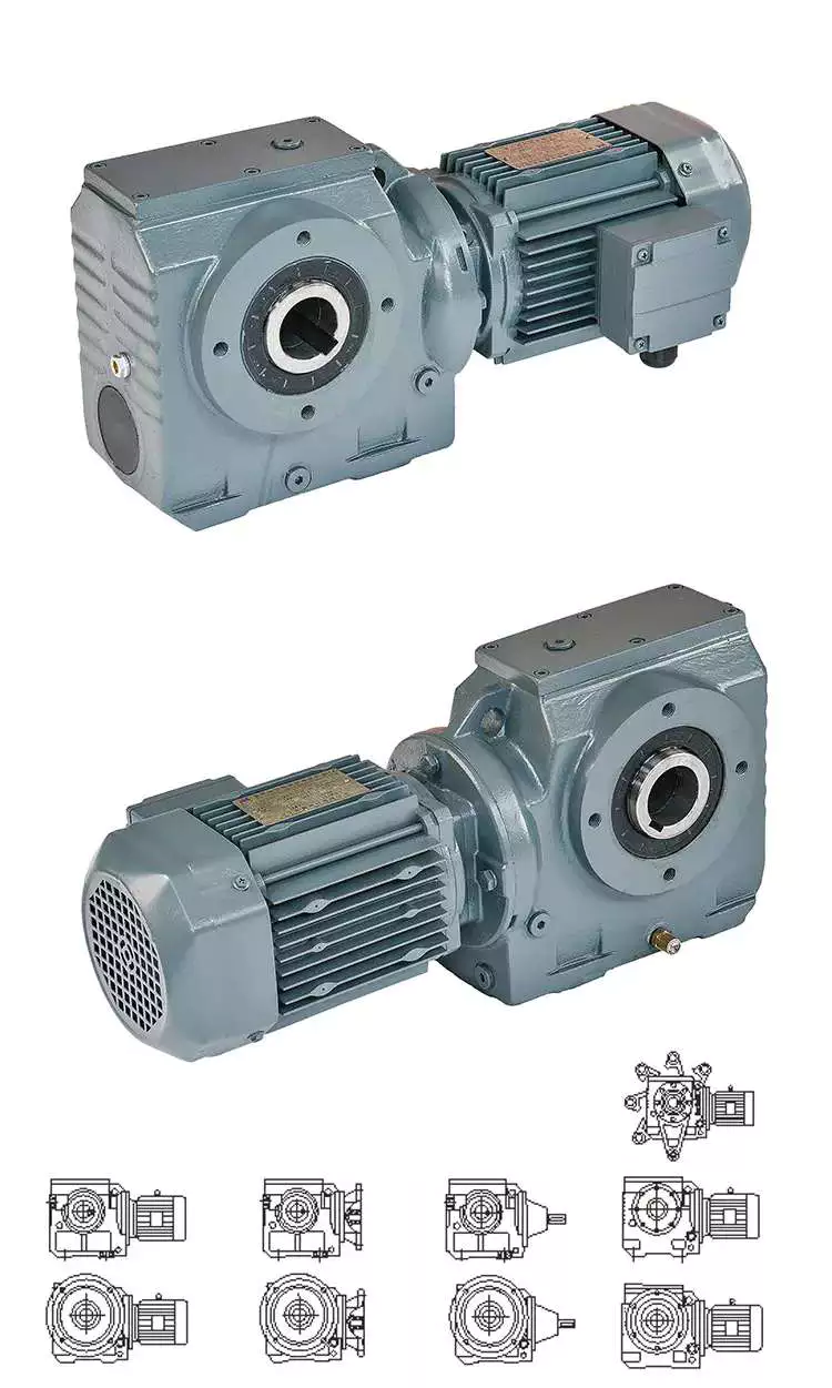 Double throat worm gear
There are a few things to consider when choosing a dual-throat worm gear. First, the diameter of the root circle must match the circle pitch of the larger gear. This measurement is usually done by measuring the distance between adjacent teeth. Alternatively, the worm’s normal module can be used. It is the value entered in the worm module dialog. In addition, the axial pitch of the worm should be equal to the pitch diameter of the circular pitch.
Double-throat worm gears are an excellent choice for heavy and heavy-duty applications. The design of this worm gear is ideal for heavy-duty applications as it provides a tighter connection between the worm and the gear. It is also more compact than other types of gear and is comparable to a fine-pitch lead screw.
The efficiency of a double-throat worm gear depends on the material of the gear and worm. Typically, gears are made of case-hardened steel, while worm gears are made of bronze or cast iron. In some cases, a combination of cast iron and bronze can be used.
The deflection of the worm shaft is also affected by the tooth parameters. Tooth height, pressure angle, and size factors all affect the deflection of the worm shaft. In addition, the number of worm threads is another important parameter that affects the deflection of the worm shaft.
Double-throat worm gears are commonly used in industrial applications where high drive reduction is required. The worm has a concave and internal tooth structure that can be adjusted to achieve various ratios. Worm gears and worm gear assemblies must be properly mounted on their shafts to prevent back drive.
Brass worm gear
The basic working principle of the brass worm gear reducer gearbox is the same as that of the traditional worm gear reducer gearbox. Its axial pitch must be equal to the circumferential pitch of the larger gear. The single-thread design advances one tooth per revolution, while the double-thread design advances two teeth. The threads on the worm are either left-handed or right-handed. The lead of a worm is the distance a point on the thread of the worm moves in one revolution. The lead angle is the angle tangent to the pitch of the cylinder and the axis of the worm.
Double-thread worm gear reducer gearboxes are best for heavy loads. It provides the tightest connection between the worm and the gear. Assembly of the worm gear requires precise mounting. The keyway installation method involves drilling a square cut in the gear hole. This prevents the worm from rotating on the shaft and helps transmit torque. Then use the set screw to secure the gear to the hub.
The large fuel tank helps keep the worm gear clean and reduces heat. It also provides lubrication for extended life. Worm gear reducer gearboxes with oil reservoirs provide a lubricated environment and low-friction surfaces. Additionally, it offers multi-position installation flexibility. Additionally, its housing is cross-milled for precise alignment. It also features internal baffles for leak-free ventilation.
I260 series worm gear reducer gearboxes are one-piece iron casings with solid or hollow output shafts and tapered roller bearings. This gear reducer gearbox is designed for low to medium-horsepower applications. This gear reducer gearbox is a cost-effective option with low initial cost, the high gear ratio, and high torque in a compact package. Also, it is more shock resistant than other gear reducer gearboxes.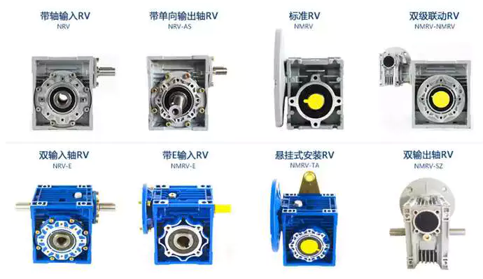 Brass worm gear
Brass worm gear reducer gearbox is a reduction gear. This type of gear can provide a lot of reduction in a small package. This type of gear reducer gearbox also has the ability to generate high torque. However, it is important to understand that this gear reducer gearbox has thermal limitations, which reduce its efficiency. The choice of lubricant for this gear reducer gearbox is very flexible. However, being a yellow metal, it is important to remember that the lubricant must be non-reactive.
Worm gears are used in many consumer and industrial applications and have high reduction ratios. These gears are produced in various configurations and sizes. Worm gears are similar to spur gears but have non-parallel shafts. Worm gears are also suitable for applications requiring low output speed but high torque.
Worm gears have some distinct advantages over other gears. First, unlike standard gears, the worm rotates in a worm-like motion. This mechanism prevents reverse movement. This is because the lead angle of the worm gear is small. Additionally, the worms self-lock, helping to prevent reversal. However, this mechanism is not entirely reliable. Worm gears can be found in elevators, fishing reels, sprockets, and automotive power steering.
Another advantage of worm gears is that they are easy to manufacture. The rationale behind this design is to have two mutually perpendicular axes. Then, two or more threads are added to the worm gear. The common tangent between these two shafts intersects the pitch line of the worm gear shaft. This is the basis of transfer speed.


editor by CX 2023-06-13