Tag Archives: motor bldc

China 2023 New high-performance BLDC motor Z4BLD60 brushless DC geared motor compact worm gearbox

Error:获取返回内容失败,
Your session has expired. Please reauthenticate.
worm reducer

What is a worm gear reducer gearbox?

The worm gear reducer gearbox is used to change the output speed of the mechanical device. It consists of worm and helical gears mounted on the input side of the equipment. In some cases, this gear reduction system can be multi-stage, enabling extremely low output speeds. It has the advantages of low energy consumption and low vibration.
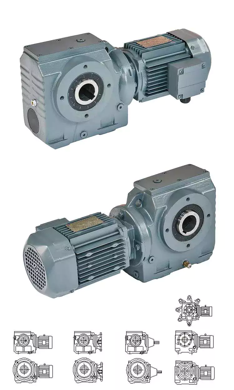
Hollow shaft worm gear reducer gearbox

Worm gear reducer gearbox is an effective device to reduce the speed of mechanical equipment. The use of hard steel or non-ferrous metals for the worm increases its efficiency. Worms made of hard steel generate more heat than worms made of mild steel. Different thermal expansion results in gaps between mating surfaces. Despite its many benefits, worm gear reducer gearboxes are prone to oil leakage, which can be a problem for a number of reasons.
Hollow shaft worm gear reducer gearboxes are available in different gear ratios and are compatible with many motor types. Some are available in dual-axis and single-axis configurations and can be mounted horizontally or vertically. They are also available in intermediate ratios, as well as four- and five-speed transmission types. They can also be connected with additional output shafts.
Another type of worm gear reducer gearbox is the multi-stage variety. This gear reducer gearbox has multiple stages, enabling it to reduce speed with extremely low output speeds. In addition to the large transmission ratio, the multi-stage gear reducer gearbox has low noise, low vibration and low energy consumption.
Worm gear reducer gearboxes offer space-saving solutions as well as increased torque. Agknx Gearbox offers worm gear reducer gearboxes that solve common deceleration problems. The company has also expanded its product range into the bathroom market. Compared with the standard gearbox, the worm gear reducer gearbox has the characteristics of lower price and better torque output.
Agknx worm gear

The Agknx type worm gear reducer gearbox has multi-tooth line contact and is widely used in heavy machinery. These gears are characterized by a high load-carrying capacity, but they are highly sensitive to misalignment and manufacturing errors. However, by employing point contact, these gears can be made more reliable and can withstand higher loads.
Another major advantage of the Agknx worm gear is its high load capacity. The tooth profile design of the gears has a high relative slip ratio, which improves efficiency and load capacity. In addition, the large angle between the sliding direction and the contact line provides a low coefficient of friction. The Agknx worm gear also features premium carburized steel and phosphor bronze castings for exceptional durability. In addition, the tooth profile is very precise, the operation is quiet, and the speed fluctuation is small.
Agknx worm gear reducer gearboxes are designed to operate for up to ten hours per day with an even load. The design of this worm gear reducer gearbox stems from Sumitomo Heavy Industries’ extensive experience in gear reducer gearboxes. The smooth surface texture and precise tooth profile of the gears ensure that the gears can withstand high loads without damaging the lubricant film. In addition, Agknx worm shafts are specially designed to have the right stiffness.
Agknx worm gear reducer gearboxes are designed to maximize load capacity while minimizing energy consumption. Its fully meshed teeth reduce surface pressure on the worm gear teeth and increase load capacity.
worm reducerDouble throat worm gear

There are a few things to consider when choosing a dual-throat worm gear. First, the diameter of the root circle must match the circle pitch of the larger gear. This measurement is usually done by measuring the distance between adjacent teeth. Alternatively, the worm’s normal module can be used. It is the value entered in the worm module dialog. In addition, the axial pitch of the worm should be equal to the pitch diameter of the circular pitch.
Double-throat worm gears are an excellent choice for heavy and heavy-duty applications. The design of this worm gear is ideal for heavy-duty applications as it provides a tighter connection between the worm and the gear. It is also more compact than other types of gear and is comparable to a fine-pitch lead screw.
The efficiency of a double-throat worm gear depends on the material of the gear and worm. Typically, gears are made of case-hardened steel, while worm gears are made of bronze or cast iron. In some cases, a combination of cast iron and bronze can be used.
The deflection of the worm shaft is also affected by the tooth parameters. Tooth height, pressure angle, and size factors all affect the deflection of the worm shaft. In addition, the number of worm threads is another important parameter that affects the deflection of the worm shaft.
Double-throat worm gears are commonly used in industrial applications where high drive reduction is required. The worm has a concave and internal tooth structure that can be adjusted to achieve various ratios. Worm gears and worm gear assemblies must be properly mounted on their shafts to prevent back drive.
Brass worm gear

The basic working principle of the brass worm gear reducer gearbox is the same as that of the traditional worm gear reducer gearbox. Its axial pitch must be equal to the circumferential pitch of the larger gear. The single-thread design advances one tooth per revolution, while the double-thread design advances two teeth. The threads on the worm are either left-handed or right-handed. The lead of a worm is the distance a point on the thread of the worm moves in one revolution. The lead angle is the angle tangent to the pitch of the cylinder and the axis of the worm.
Double-thread worm gear reducer gearboxes are best for heavy loads. It provides the tightest connection between the worm and the gear. Assembly of the worm gear requires precise mounting. The keyway installation method involves drilling a square cut in the gear hole. This prevents the worm from rotating on the shaft and helps transmit torque. Then use the set screw to secure the gear to the hub.
The large fuel tank helps keep the worm gear clean and reduces heat. It also provides lubrication for extended life. Worm gear reducer gearboxes with oil reservoirs provide a lubricated environment and low-friction surfaces. Additionally, it offers multi-position installation flexibility. Additionally, its housing is cross-milled for precise alignment. It also features internal baffles for leak-free ventilation.
I260 series worm gear reducer gearboxes are one-piece iron casings with solid or hollow output shafts and tapered roller bearings. This gear reducer gearbox is designed for low to medium-horsepower applications. This gear reducer gearbox is a cost-effective option with low initial cost, the high gear ratio, and high torque in a compact package. Also, it is more shock resistant than other gear reducer gearboxes.
worm reducerBrass worm gear

Brass worm gear reducer gearbox is a reduction gear. This type of gear can provide a lot of reduction in a small package. This type of gear reducer gearbox also has the ability to generate high torque. However, it is important to understand that this gear reducer gearbox has thermal limitations, which reduce its efficiency. The choice of lubricant for this gear reducer gearbox is very flexible. However, being a yellow metal, it is important to remember that the lubricant must be non-reactive.
Worm gears are used in many consumer and industrial applications and have high reduction ratios. These gears are produced in various configurations and sizes. Worm gears are similar to spur gears but have non-parallel shafts. Worm gears are also suitable for applications requiring low output speed but high torque.
Worm gears have some distinct advantages over other gears. First, unlike standard gears, the worm rotates in a worm-like motion. This mechanism prevents reverse movement. This is because the lead angle of the worm gear is small. Additionally, the worms self-lock, helping to prevent reversal. However, this mechanism is not entirely reliable. Worm gears can be found in elevators, fishing reels, sprockets, and automotive power steering.
Another advantage of worm gears is that they are easy to manufacture. The rationale behind this design is to have two mutually perpendicular axes. Then, two or more threads are added to the worm gear. The common tangent between these two shafts intersects the pitch line of the worm gear shaft. This is the basis of transfer speed.

China 2023 New high-performance BLDC motor Z4BLD60 brushless DC geared motor     compact worm gearboxChina 2023 New high-performance BLDC motor Z4BLD60 brushless DC geared motor     compact worm gearbox
editor by Cx 2023-07-06

China Bldc Motor Geared Escooter 24V DC Nema17 Worm Geared Electric Motors 18W 3.2RPM CE ROHS Approved with high quality

Error:获取返回内容失败,
Your session has expired. Please reauthenticate.

Advantages and disadvantages of worm gear reducer gearbox

If you are looking for a worm gear reducer gearbox, you have come to the right place. This article will cover the pros and cons of worm gear reducer gearboxes and discuss the different types available. You will learn about multi-head worm gear reducer gearboxes, hollow shaft worm gear reducer gearboxes as well as hypoid gear sets and motors.
worm reducer

Hollow shaft worm gear reducer gearbox

Hollow shaft worm gear reducer gearboxes are used to connect two or more rotating parts. They are available in single-axis and dual-axis versions and can be connected to various motor types. They can also have different ratios. The ratios of these gear reducer gearboxes depend on the quality of the bearings and assembly process.
Hollow shaft worm gear reducer gearboxes are made of bronze worm gears and cast iron hubs. The gears are lubricated with synthetic oil. They are lightweight and durable. They can be installed in various engine housings. Additionally, these gear reducer gearboxes are available in a variety of sizes. The range includes 31.5, 40, 50, 63, and 75mm models. Other sizes are available upon request.
In addition to worm gear reducer gearboxes, there are also helical gear reducer gearboxes. These reducer gearboxes can achieve very low output speeds. They are also suitable for all-around installations. In addition, the advantage of a multi-stage reducer gearbox is that it is more efficient than a single-stage gear reducer gearbox. They also feature low noise, low vibration, and low energy consumption.
Hollow shaft worm gear reducer gearboxes are generally less expensive and last longer. They are also a suitable replacement for solid shaft gearboxes for machines that require high torque without compromising strength. Typical gear arrangements include worm, spur, helical and bevel gears. Gear ratio is the ratio of input torque to output torque.

Multi-head worm gear reducer gearbox

The multi-head worm gear reducer gearbox is used to reduce the speed of the machine. It uses friction to hold the worm in place while transmitting power. These gears can also be called ground worms and hardened worm gears. They are useful in conveying systems and most engineering applications.
Multiple worm reducer gearboxes have a large number of gear ratios. These gear designs have a central cross-section that forms the front and rear boundaries of the worm gear. This design is a better choice than other worm gears because it is less prone to wear and can be used with a variety of motors and other electronics.
Adjustable multi-head worm gear reducer gearbox to reduce axial play. Usually, the backlash on the left and right sides of the worm is the same. However, if you need less backlash, you can buy a double lead worm gear. This design is ideal for precision applications requiring small clearances. The lead of the opposing teeth of the double worm gear is different from the right side, so the backlash can be adjusted without adjusting the center distance between the worm gears.
Worm gear reducer gearboxes are available from a variety of manufacturers. Many gear manufacturers stock these gears. Since the gear ratios are standardized, there is no need to adjust the height, diameter, or length of the shaft. Worm gears have fewer moving parts, which means they require less maintenance.
worm reducer

Hypoid Gear Set

Worm gears are the most common type of gear. While these gears are great for high-to-low ratios, hypoid gear sets are much more efficient in all ratios. This difference is due to higher torque density, better geometry and materials, and the way hypoid gears transmit force differently than worm gears.
Hypoid gear sets have curved helical teeth. This results in smooth gear meshing and little noise. This is because the hypoid gears start to slowly contact each other, but the contact progresses smoothly from tooth to tooth. This reduces friction and wears, thereby increasing the efficiency of the machine.
The main advantages of hypoid gears over worm gears are higher torque capacity and lower noise levels. Although their upfront cost may be higher, hypoid gears are more efficient than worm gears. They are able to handle higher initial inertia loads and can deliver more torque with a smaller motor. This saves money in the long run.
Another advantage of hypoid gears is the lower operating temperature. They also do not require oil lubrication or ventilation holes, reducing maintenance requirements. The hypoid gear set is maintenance-free, and the grease on the hypoid gear set lasts for decades.

Hypoid gear motor

A hypoid gear motor is a good choice for a worm gear reducer gearbox as it allows for a smaller motor and more efficient energy transfer. In fact, a 1 hp motor driving a hypoid reducer gearbox can provide the same output as a 1/2 hp motor driving a worm reducer gearbox. A study by Agknx compared two gear reduction methods and determined that a hypoid gear motor produces more torque and power than a worm reducer gearbox when using a fixed reduction ratio of 60:1. The study also showed that the 1/2 HP hypoid gear motor is more energy efficient and reduces electricity bills.
Worm reducer gearboxes run hotter than hypoid gears, and the added heat can shorten their lifespan. This can cause components to wear out faster, and the motor may require more frequent oil changes. In addition, hypoid gear motors are more expensive to manufacture.
Compared to worm gears, hypoid gears offer higher efficiency and lower operating noise. However, they require additional processing techniques. They are made of bronze, a softer metal capable of absorbing heavy shock loads. Worm drives require work hardening and are less durable. Operating noise is reduced by up to 30%, and hypoid gears are less prone to breakage than bevel gears.
Hypoid gear motors are prized for their efficiency and are used in applications requiring lower torque. A unique hypoid tooth profile reduces friction. In addition, hypoid gear motors are ideal for applications where space is limited. These geared motors are often used with pulleys and levers.

R series worm gear reducer gearbox

R series worm gear reducer gearboxes have a variety of characteristics that make them ideal for different applications. Its high rigidity cast iron housing and rigid side gears are designed for smooth drive and low noise. It also features high load capacity and long service life. Additionally, it can be assembled into many different configurations as required.
High efficiency, large output torque and good use efficiency. It comes in four basic models ranging from 0.12KW to 200KW. It can be matched with right angle bevel gearbox to provide large speed ratio and high torque. This combination is also suitable for low output and high torque.
worm reducer

AGKNX Electric Worm Gear reducer gearbox

AGKNX Electric worm gear reducer gearboxes are available with NEMA C-face mounting flanges for a variety of motors. These reducer gearboxes feature double lip oil seals, an aluminum alloy housing, and two bearings on the input and output shafts. These reducer gearboxes are rust-proof and have epoxy paint on the inside. They are available in a variety of ratios, from 7.5:1 to 100:1.
Worm reducer gearboxes are one of the most cost-effective and compact gears. These reducer gearboxes increase output torque while reducing input speed. AGKNX Electric’s worm gear reducer gearboxes are pre-installed with Mobil SHC634 Synthetic Gear Oil. These reducer gearboxes have an internal oil gallery guide to protect the shaft. They also have a one-piece cast iron housing.
AGKNX Electric Corporation is the leading independent distributor of electric motors in the United States. They have eight strategically located warehouses, enabling them to ship most orders on the same day. They offer motors of various sizes up to 20,000 hp. They also offer a variety of motor controls and variable speed drives.
China Bldc Motor Geared Escooter 24V DC Nema17 Worm Geared Electric Motors 18W 3.2RPM CE ROHS Approved     with high quality China Bldc Motor Geared Escooter 24V DC Nema17 Worm Geared Electric Motors 18W 3.2RPM CE ROHS Approved     with high quality
editor by czh 2023-02-10

China Custom BLDC DC Brushless Gear Motor with Gear Circular Shaft Ear Flat Hollow Screw Hole Through Hole Right Angle Hollow Solid Worm Gearbox with high quality

Product Description

DC Blushless Gear Motor
G 2 BLD(P) 40 220 GN 30S
Enterprise Code Mounting Flange Motor Type Output Power Voltage Shape of Motor Shaft Motor Speed
G – GPG 2-60mm
3-70mm
4-80mm
5-90mm
6-100mm
BLD – Brushless motor
            with square gearbox

BLDP – Brushless motor
              with planetary gearbox 

10 – 10W
15 – 15W
25 – 25W
40 – 40W
60 – 60W
90 – 90W
200 – 200W
400 – 400W
24 – DC24V
36 – DC36V
48 – DC48V
110 – DC110V
220 – DC220V
GN – General Helival Gear
GU – Reinforced Helival Gear
A1 – Milling Keyway
A – Flat type
15S – 1500RPM
18S – 1800RPM
25S – 2500RPM
30S – 3000RPM
Gearbox
2 GN 50 RT
Model & Dimension Gear Type Reduction Ratio Bearing Type
2: 60mm
4: 80mm
5: 90mm
6: 104mm
GN: General Helical Gear
GU: Reinforced Helical Gear
50: Reduction Ratio 1:50
10X Denotes The Mid-gearbox Ration 1:10
RT – Right Angle
RC – Right-Angle Hollow
5 GFS 100 K 20
Model & Dimension Gear Type Reduction Ratio Bearing Type Out-shaft Diameter
2: 60mm
4: 80mm
5: 90mm
6: 100mm
Flat Boxes
Hollow Output
100
The reduction ratio of reducer can be said speed ratio range, for example, 50-75, may also be a separate ratio,
for example 100
K: standard rolling bearing
H: sliding bearing
L: axle type
Z: hybrid bearings
20: Φ20mm

Motor Performance Parameters
Model Voltage No-load Current No-load Speed Rated Power Rated Current Rated Speed Rated Torque Grade Protection
V A RPM W A RPM N.m IP
G2BLD25-24GN-30S 24 MAX 0.4 3200 25 1.3 3000 0.08 44
G2BLD25-36GN-30S 36 MAX 0.3 0.9
G2BLD25-48GN-30S 48 MAX 0.2 0.7
Motor Model
Type Pinion Shaft Round Shaft
Lead Wire G2BLD200-24GN-30S G2BLD200-24A1-30S
G2BLD200-36GN-30S G2BLD200-36A1-30S
G2BLD200-48GN-30S G2BLD200-48A1-30S
Parallel Shaft Gearhead (Sold Separately)
Gearhead Type Gearhead Model Gear Ratio
Long Life, Low Noise 2GN/GU _ RC/RT 3, 3.6, 5, 6, 7.5, 9, 12.5, 15, 18,
25, 30, 36, 50, 60, 75, 90,
100, 120, 150, 180, 200
2GN10XK ( Decimal Gearhead ) 
Allowance Torque Unit: Upside (N-m) / Belowside (kgf.cm)
Gear Ratio 3 3.6 5 6 7.5 9 12.5 15 18 25 30 36 50 60 75 90 100 120 150 180 200
r/min Output Shaft Speed 1000 830 600 500 400 330 240 200 166 120 100 83 60 50 40 33 30 25 20 16 15
GU Allowance Torque N·m  0.19 0.23 0.32 0.38 0.48 0.58 0.81 0.87 1.16 1.44 1.73 2.07 2.52 3 3 3 3 3 3 3 3

FAQ
Q: How about your company?
A: We are a gear motor factory established in 1995 and located in HangZhou city of china. 
     We have more than 1200 workers. Our main product is AC micro gear motor 6W to 250W, 
     AC small gear motor 100W to 3700W, brush DC motor 10W to 400W, brushless motor10W to 750W,
     drum motor 60W to 3700W, planetary gearbox,and worm gearbox,etc.

Q: How about your quality control?
A: From raw material to finished products, we have strict and complete IPQC. 
     And the advanced test-ing machine can assure of qualified products delivered.

Q: How to choose a suitable motor?
A: If you have gear motor pictures or drawings to show us, 
    or you tell us detailed specs like volt-age, speed, torque, motor size, the working model of the motor, needed lifetime and noise level, etc. 
    please do not hesitate to let us know, then we can suggest a suitable motor per your request.

Q: Can you make the gear motor with customizing specifications?
A: Yes, we can customize per your request for the voltage, speed, torque, and shaft size and shape. 
     if you need additional wires or cables soldered on the terminal or need to add connectors, or capacitors, or EMC we can make it too.

Q: What’s your lead time?
A: Usually our regular standard product will need 10-15days, a bit longer for customized products. 
     But we are very flexible on the lead time, it will depend on the specific orders.

Q: What is your MOQ?
A: If delivered by sea, the minimum order is 100 pieces, if deliver by express, there is no limit.

Q: Do you have the item in stock?
A: l am sorry we do not have the item in stock, All products are made with orders.

Q: How to contact us?
A: You can send us an inquiry.


Lead Screws and Clamp Style Collars

If you have a lead screw, you’re probably interested in learning about the Acme thread on this type of shaft. You might also be interested in finding out about the Clamp style collars and Ball screw nut. But before you buy a new screw, make sure you understand what the terminology means. Here are some examples of screw shafts:

Acme thread

The standard ACME thread on a screw shaft is made of a metal that is resistant to corrosion and wear. It is used in a variety of applications. An Acme thread is available in a variety of sizes and styles. General purpose Acme threads are not designed to handle external radial loads and are supported by a shaft bearing and linear guide. Their design is intended to minimize the risk of flank wedging, which can cause friction forces and wear. The Centralizing Acme thread standard caters to applications without radial support and allows the thread to come into contact before its flanks are exposed to radial loads.
The ACME thread was first developed in 1894 for machine tools. While the acme lead screw is still the most popular screw in the US, European machines use the Trapezoidal Thread (Metric Acme). The acme thread is a stronger and more resilient alternative to square threads. It is also easier to cut than square threads and can be cut by using a single-point threading die.
Similarly to the internal threads, the metric versions of Acme are similar to their American counterparts. The only difference is that the metric threads are generally wider and are used more frequently in industrial settings. However, the metric-based screw threads are more common than their American counterparts worldwide. In addition, the Acme thread on screw shafts is used most often on external gears. But there is still a small minority of screw shafts that are made with a metric thread.
ACME screws provide a variety of advantages to users, including self-lubrication and reduced wear and tear. They are also ideal for vertical applications, where a reduced frictional force is required. In addition, ACME screws are highly resistant to back-drive and minimize the risk of backlash. Furthermore, they can be easily checked with readily available thread gauges. So, if you’re looking for a quality ACME screw for your next industrial project, look no further than ACME.
screwshaft

Lead screw coatings

The properties of lead screw materials affect their efficiency. These materials have high anti-corrosion, thermal resistance, and self-lubrication properties, which eliminates the need for lubrication. These coating materials include polytetrafluoroethylene (PFE), polyether ether ketone (PEK), and Vespel. Other desirable properties include high tensile strength, corrosion resistance, and rigidity.
The most common materials for lead screws are carbon steel, stainless steel, and aluminum. Lead screw coatings can be PTFE-based to withstand harsh environments and remove oil and grease. In addition to preventing corrosion, lead screw coatings improve the life of polymer parts. Lead screw assembly manufacturers offer a variety of customization options for their lead screw, including custom-molded nuts, thread forms, and nut bodies.
Lead screws are typically measured in rpm, or revolutions per minute. The PV curve represents the inverse relationship between contact surface pressure and sliding velocity. This value is affected by the material used in the construction of the screw, lubrication conditions, and end fixity. The critical speed of lead screws is determined by their length and minor diameter. End fixity refers to the support for the screw and affects its rigidity and critical speed.
The primary purpose of lead screws is to enable smooth movement. To achieve this, lead screws are usually preloaded with axial load, enabling consistent contact between a screw’s filets and nuts. Lead screws are often used in linear motion control systems and feature a large area of sliding contact between male and female threads. Lead screws can be manually operated or mortised and are available in a variety of sizes and materials. The materials used for lead screws include stainless steel and bronze, which are often protected by a PTFE type coating.
These screws are made of various materials, including stainless steel, bronze, and various plastics. They are also made to meet specific requirements for environmental conditions. In addition to lead screws, they can be made of stainless steel, aluminum, and carbon steel. Surface coatings can improve the screw’s corrosion resistance, while making it more wear resistant in tough environments. A screw that is coated with PTFE will maintain its anti-corrosion properties even in tough environments.
screwshaft

Clamp style collars

The screw shaft clamp style collar is a basic machine component, which is attached to the shaft via multiple screws. These collars act as mechanical stops, load bearing faces, or load transfer points. Their simple design makes them easy to install. This article will discuss the pros and cons of this style of collar. Let’s look at what you need to know before choosing a screw shaft clamp style collar. Here are some things to keep in mind.
Clamp-style shaft collars are a versatile mounting option for shafts. They have a recessed screw that fully engages the thread for secure locking. Screw shaft clamp collars come in different styles and can be used in both drive and power transmission applications. Listed below are the main differences between these 2 styles of collars. They are compatible with all types of shafts and are able to handle axial loads of up to 5500 pounds.
Clamp-style shaft collars are designed to prevent the screw from accidentally damaging the shaft when tightened. They can be tightened with a set screw to counteract the initial clamping force and prevent the shaft from coming loose. However, when tightening the screw, you should use a torque wrench. Using a set screw to tighten a screw shaft collar can cause it to warp and reduce the surface area that contacts the shaft.
Another key advantage to Clamp-style shaft collars is that they are easy to install. Clamp-style collars are available in one-piece and two-piece designs. These collars lock around the shaft and are easy to remove and install. They are ideal for virtually any shaft and can be installed without removing any components. This type of collar is also recommended for those who work on machines with sensitive components. However, be aware that the higher the OD, the more difficult it is to install and remove the collar.
Screw shaft clamp style collars are usually one-piece. A two-piece collar is easier to install than a one-piece one. The two-piece collars provide a more effective clamping force, as they use the full seating torque. Two-piece collars have the added benefit of being easy to install because they require no tools to install. You can disassemble one-piece collars before installing a two-piece collar.
screwshaft

Ball screw nut

The proper installation of a ball screw nut requires that the nut be installed on the center of the screw shaft. The return tubes of the ball nut must be oriented upward so that the ball nut will not overtravel. The adjusting nut must be tightened against a spacer or spring washer, then the nut is placed on the screw shaft. The nut should be rotated several times in both directions to ensure that it is centered.
Ball screw nuts are typically manufactured with a wide range of preloads. Large preloads are used to increase the rigidity of a ball screw assembly and prevent backlash, the lost motion caused by a clearance between the ball and nut. Using a large amount of preload can lead to excessive heat generation. The most common preload for ball screw nuts is 1 to 3%. This is usually more than enough to prevent backlash, but a higher preload will increase torque requirements.
The diameter of a ball screw is measured from its center, called the ball circle diameter. This diameter represents the distance a ball will travel during 1 rotation of the screw shaft. A smaller diameter means that there are fewer balls to carry the load. Larger leads mean longer travels per revolution and higher speeds. However, this type of screw cannot carry a greater load capacity. Increasing the length of the ball nut is not practical, due to manufacturing constraints.
The most important component of a ball screw is a ball bearing. This prevents excessive friction between the ball and the nut, which is common in lead-screw and nut combinations. Some ball screws feature preloaded balls, which avoid “wiggle” between the nut and the ball. This is particularly desirable in applications with rapidly changing loads. When this is not possible, the ball screw will experience significant backlash.
A ball screw nut can be either single or multiple circuits. Single or multiple-circuit ball nuts can be configured with 1 or 2 independent closed paths. Multi-circuit ball nuts have 2 or more circuits, making them more suitable for heavier loads. Depending on the application, a ball screw nut can be used for small clearance assemblies and compact sizes. In some cases, end caps and deflectors may be used to feed the balls back to their original position.

China Custom BLDC DC Brushless Gear Motor with Gear Circular Shaft Ear Flat Hollow Screw Hole Through Hole Right Angle Hollow Solid Worm Gearbox   with high qualityChina Custom BLDC DC Brushless Gear Motor with Gear Circular Shaft Ear Flat Hollow Screw Hole Through Hole Right Angle Hollow Solid Worm Gearbox   with high quality