Product Description
Product Description
Z LYJ gearbox series are transmission devices, which are specially designed for single-screw extruder with high precision, hard gear surface, accompany with thrust. Adopting the technical specifications stipulated in JB/T9050. 1-1999, all CHINAMFG gearboxes are designed accordingly.
Product Parameters
Detailed Photos
Machine Parts
Name: High Quality CHINAMFG Gearbox
Original: China Gear material: high alloy steel low carbon (20CrMnTi)The interface is hardened, precision-ground and hard-chrome-plated to 870HV hardness and Ra 0.8-1.6µm roughness, so the shaft-seal is super hard, resists wear and corrosion, and very durable.
Main Features
Made of carburizing steel (Forging), go through normalization heat treatment for forged carburizing steel; and gear faces are also nitride-treated to at least 60HRC hardness for optimal rigidity and carburizing depth 0.8-1.1MM and wear resistance.
Single Screw Extruder Gearbox
Our CHINAMFG gearbox for single screw extruder adopts high strength alloy steel material and the gear is of high accuracy. It is less
noisy, work quietly and smoothly. So it is a longer service life.
Gearbox casting body
1. we prepare enough casting body in our workshop to guarantee the delivery time.
2. this is our new gearbox casting body design.
3. fast delivery time and high quality
Heat treatment furnace
We have own heat treatment for the gears and gearshaft, so it’s easy for us to control the quality and the quality is more gurantee.
Packaging & Shipping
1)Packing: Wrapped up by film in wooden cases
2)Port Departure: HangZhou Port
3)Delivery time: 25 working days CHINAMFG receipt of 30% deposit(days based on your quantity)
We use strong plywood or wooden case for all our products.
FAQ
Q1. Are you a trading company or a manufacturer?
We are a BSCI&ISO-9001 certificated manufacturer.
Q2. Can I place the customized order for different sizes, colors, materials,packings….?
Yes, all the customized orders are welcomed.
Q3. Could I get a QC report before delivery?
Yes, the specific QC reports will be sent to you before delivery.
Q4. Can I get a lower price if I place a larger order?
Yes, the price will be modified according to your order quantities.
/* January 22, 2571 19:08:37 */!function(){function s(e,r){var a,o={};try{e&&e.split(“,”).forEach(function(e,t){e&&(a=e.match(/(.*?):(.*)$/))&&1
| Standard: | DIN, ASTM |
|---|---|
| Technics: | Casting |
| Material: | Metal |
| After-Sales Service: | Good After-Sales Service |
| Warranty: | One Year |
| Feature: | Corrosion Resistance |
| Customization: |
Available
|
|
|---|
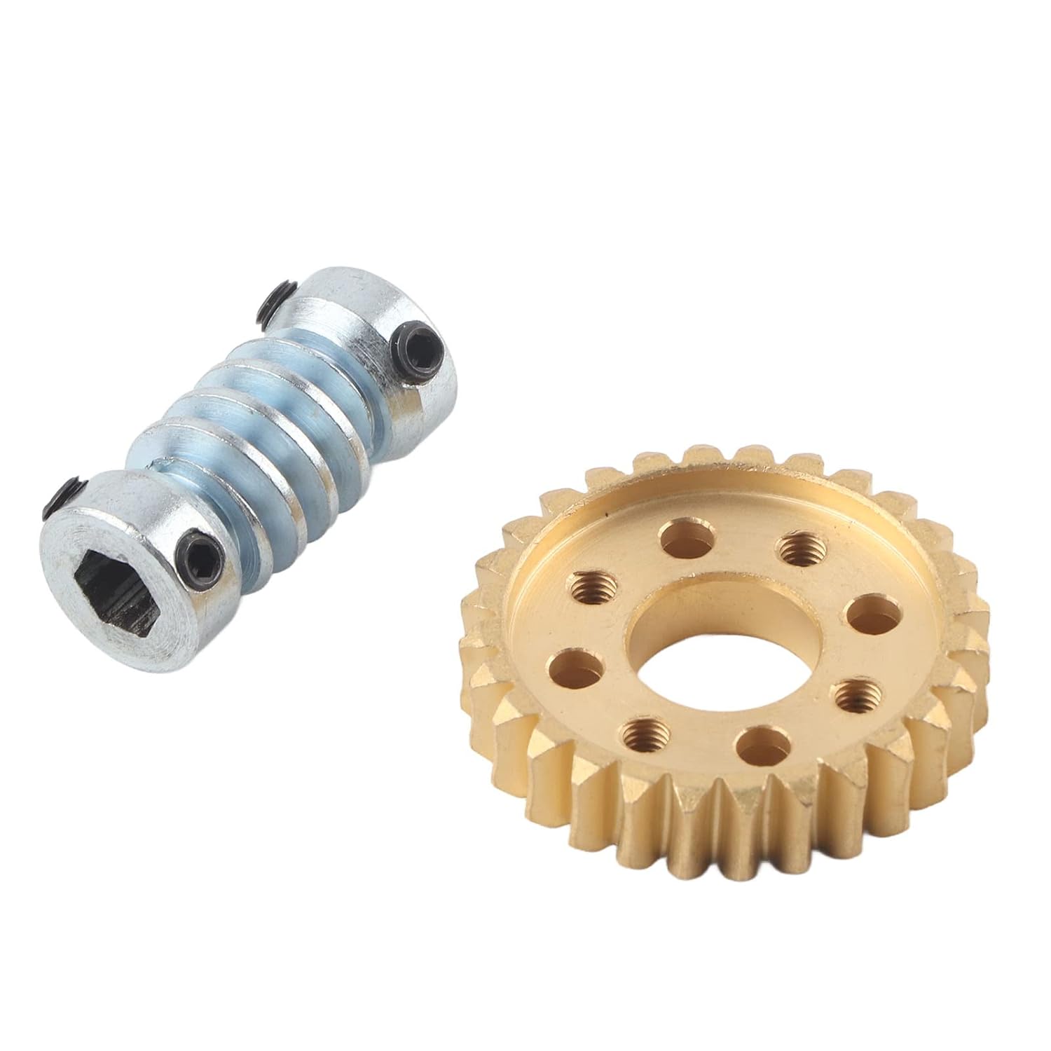
How do you properly lubricate a worm screw and gear assembly?
Proper lubrication is essential for the smooth and efficient operation of a worm screw and gear assembly. Lubrication helps reduce friction, wear, and heat generation between the contacting surfaces, thereby extending the lifespan of the components. Here are the steps to properly lubricate a worm screw and gear assembly:
- Clean the Assembly: Before applying lubrication, ensure that the worm screw and gear assembly is free from dirt, debris, and old lubricant residues. Clean the surfaces using an appropriate cleaning agent or solvent, followed by a thorough drying process.
- Select the Right Lubricant: Choose a lubricant specifically designed for gear systems or worm screw applications. Consider factors such as viscosity, temperature range, load capacity, and compatibility with the materials used in the assembly. Consult the manufacturer’s recommendations or lubrication guidelines for the specific assembly to determine the suitable lubricant type and grade.
- Apply the Lubricant: Apply the lubricant to the contacting surfaces of the worm screw and gear assembly. Use an appropriate applicator, such as a brush, oil can, or grease gun, depending on the lubricant form (oil or grease) and the accessibility of the components. Ensure complete coverage of the gear teeth, worm screw threads, and other relevant surfaces. Pay attention to areas where the most significant friction and wear occur.
- Monitor the Lubricant Level: Check the lubricant level regularly to ensure an adequate supply. Depending on the application and operating conditions, lubricant consumption or degradation may occur over time. It is important to maintain the lubricant level within the recommended range to ensure proper lubrication and prevent excessive wear or overheating.
- Periodic Lubrication Maintenance: Establish a lubrication maintenance schedule based on the operating conditions and manufacturer’s recommendations. Regularly inspect the assembly for signs of lubricant degradation, contamination, or insufficient lubrication. Replace the lubricant as needed and follow the recommended intervals for lubricant replenishment or reapplication.
- Consideration for Grease Lubrication: If using grease as the lubricant, it is important to choose a high-quality grease suitable for worm screw applications. Grease provides better adhesion to surfaces and tends to stay in place, offering longer-lasting lubrication compared to oil. However, excessive grease accumulation or over-greasing should be avoided, as it can lead to increased friction and inefficiency.
It is crucial to follow the manufacturer’s guidelines and recommendations for lubrication specific to the worm screw and gear assembly. Different assemblies may have unique lubrication requirements based on their design, load capacity, operating conditions, and materials used. By properly lubricating the worm screw and gear assembly, you can ensure optimal performance, reduce wear, and extend the operational life of the components.
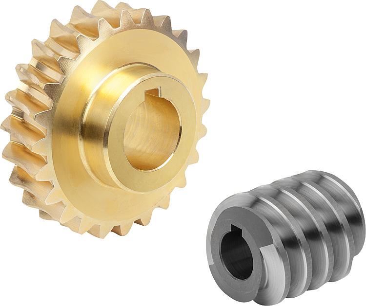
What are the latest innovations in worm screw design and materials?
In recent years, there have been several notable innovations in worm screw design and materials that aim to improve performance, efficiency, durability, and overall functionality. Here are some of the latest advancements in this field:
- Advanced Materials: One of the significant trends in worm screw design is the use of advanced materials. Manufacturers are exploring materials with enhanced strength, wear resistance, and fatigue properties. For example, advanced alloys and composite materials are being employed to improve load capacity, reduce weight, and increase the longevity of worm screws. Additionally, advancements in material science and engineering are leading to the development of self-lubricating materials, which can minimize friction and improve efficiency by reducing the need for external lubrication.
- Improved Thread Geometries: Innovations in thread geometries have focused on optimizing load distribution, reducing friction, and improving efficiency. Researchers and engineers are developing novel thread profiles and forms that enhance contact between the worm screw and the worm wheel. These designs help minimize backlash, increase load-carrying capacity, and improve overall system performance. Additionally, advancements in computer simulations and modeling techniques enable more accurate analysis and optimization of thread geometries for specific applications.
- Surface Treatments and Coatings: Surface treatments and coatings are being applied to worm screws to enhance their performance and durability. For instance, advanced coatings such as diamond-like carbon (DLC) coatings or specialized lubricious coatings help reduce friction, improve wear resistance, and minimize the need for external lubrication. Surface treatments like nitriding or carburizing can improve hardness and provide resistance against abrasive wear, increasing the lifespan of worm screws.
- Precision Manufacturing: Innovations in manufacturing processes and technologies have enabled the production of worm screws with higher precision and tighter tolerances. Advanced machining techniques, such as CNC grinding and high-precision gear hobbing, allow for the creation of worm screws with superior dimensional accuracy, improved surface finish, and better tooth profile control. These manufacturing advancements contribute to enhanced performance, reduced backlash, and increased overall system efficiency.
- Computer-Aided Design and Simulation: The use of computer-aided design (CAD) software and simulation tools has revolutionized worm screw design and optimization. Engineers can now create virtual models, simulate the behavior of worm gear systems, and analyze various design parameters to optimize performance before physical prototypes are manufactured. This iterative design process helps reduce development time, minimize costs, and improve the final design and performance of worm screws.
- Integration with Digitalization and Automation: The integration of worm gear systems with digitalization and automation technologies is another area of innovation. Worm screws are being designed to work seamlessly with sensor technologies, allowing for real-time monitoring of performance parameters such as temperature, vibration, and load. This data can be utilized for predictive maintenance, condition monitoring, and optimization of the overall system performance.
It’s important to note that the field of worm screw design and materials is continuously evolving, and new innovations are being introduced regularly. Keeping up with the latest research, advancements, and industry developments is crucial for engineers, designers, and manufacturers involved in worm gear system applications.
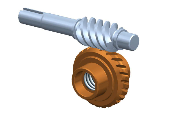
How do you calculate the gear ratio for a worm screw and gear setup?
In a worm screw and gear setup, the gear ratio is determined by the number of teeth on the worm wheel (gear) and the number of threads on the worm screw. The gear ratio represents the relationship between the rotational speed of the worm screw and the resulting rotational speed of the worm wheel. The formula to calculate the gear ratio is as follows:
Gear Ratio = Number of Teeth on Worm Wheel / Number of Threads on Worm Screw
Here’s a step-by-step process to calculate the gear ratio:
- Count the number of teeth on the worm wheel. This can be done by visually inspecting the gear or referring to its specifications.
- Count the number of threads on the worm screw. The threads refer to the number of complete turns or helical grooves wrapped around the cylindrical body of the worm screw.
- Divide the number of teeth on the worm wheel by the number of threads on the worm screw.
- The result of the division is the gear ratio. It represents the number of revolutions of the worm screw required to complete one revolution of the worm wheel.
For example, let’s say the worm wheel has 40 teeth, and the worm screw has 2 threads. Using the formula, we can calculate the gear ratio as follows:
Gear Ratio = 40 teeth / 2 threads = 20
In this case, for every full revolution of the worm screw, the worm wheel will rotate 1/20th of a revolution. This indicates a significant speed reduction, resulting in high torque output at the worm wheel.
It’s important to note that the gear ratio calculated using this formula assumes an ideal scenario without considering factors like friction, efficiency losses, or the pitch diameter of the gears. In practical applications, these factors may affect the actual gear ratio and performance of the worm screw and gear setup.


editor by CX 2024-03-03
China 15003500 MM Large Format Solar photovoltaic Screen Frame Net Puller Automatic Screen Stretching Machine worm gearbox application
Applicable Industries: Producing Plant, Printing Outlets, Circuit board printing industry, Electronic business, Solar photovoltaic business, Printing&dyeing textile printing, Glass printing, Liquid crystal contact display screen sector
Showroom Place: Viet Nam, Brazil, Thailand, Malaysia, China
Video clip outgoing-inspection: Supplied
Equipment Take a look at Report: Offered
Marketing Variety: Normal Solution
Warranty of main parts: 2 many years
Main Components: PLC, Engine, Bearing, Gearbox, Motor, Gear, Rubber
Condition: New
Kind: Typical Plate Processor
Computerized Quality: Automated
Voltage: 380V
Dimension(L*W*H): 25mm 26T36T Two Sprockets Direct Mount 11S12S Mountain Bicycle Improve with Bottom Bracket polyester mesh,Japanese NBC mesh and other domestic or imported mesh.
What is a worm gear reducer gearbox?
The worm gear reducer gearbox is used to change the output speed of the mechanical device. It consists of worm and helical gears mounted on the input side of the equipment. In some cases, this gear reduction system can be multi-stage, enabling extremely low output speeds. It has the advantages of low energy consumption and low vibration.
Hollow shaft worm gear reducer gearbox
Worm gear reducer gearbox is an effective device to reduce the speed of mechanical equipment. The use of hard steel or non-ferrous metals for the worm increases its efficiency. Worms made of hard steel generate more heat than worms made of mild steel. Different thermal expansion results in gaps between mating surfaces. Despite its many benefits, worm gear reducer gearboxes are prone to oil leakage, which can be a problem for a number of reasons.
Hollow shaft worm gear reducer gearboxes are available in different gear ratios and are compatible with many motor types. Some are available in dual-axis and single-axis configurations and can be mounted horizontally or vertically. They are also available in intermediate ratios, as well as four- and five-speed transmission types. They can also be connected with additional output shafts.
Another type of worm gear reducer gearbox is the multi-stage variety. This gear reducer gearbox has multiple stages, enabling it to reduce speed with extremely low output speeds. In addition to the large transmission ratio, the multi-stage gear reducer gearbox has low noise, low vibration and low energy consumption.
Worm gear reducer gearboxes offer space-saving solutions as well as increased torque. Agknx Gearbox offers worm gear reducer gearboxes that solve common deceleration problems. The company has also expanded its product range into the bathroom market. Compared with the standard gearbox, the worm gear reducer gearbox has the characteristics of lower price and better torque output.
Agknx worm gear
The Agknx type worm gear reducer gearbox has multi-tooth line contact and is widely used in heavy machinery. These gears are characterized by a high load-carrying capacity, but they are highly sensitive to misalignment and manufacturing errors. However, by employing point contact, these gears can be made more reliable and can withstand higher loads.
Another major advantage of the Agknx worm gear is its high load capacity. The tooth profile design of the gears has a high relative slip ratio, which improves efficiency and load capacity. In addition, the large angle between the sliding direction and the contact line provides a low coefficient of friction. The Agknx worm gear also features premium carburized steel and phosphor bronze castings for exceptional durability. In addition, the tooth profile is very precise, the operation is quiet, and the speed fluctuation is small.
Agknx worm gear reducer gearboxes are designed to operate for up to ten hours per day with an even load. The design of this worm gear reducer gearbox stems from Sumitomo Heavy Industries’ extensive experience in gear reducer gearboxes. The smooth surface texture and precise tooth profile of the gears ensure that the gears can withstand high loads without damaging the lubricant film. In addition, Agknx worm shafts are specially designed to have the right stiffness.
Agknx worm gear reducer gearboxes are designed to maximize load capacity while minimizing energy consumption. Its fully meshed teeth reduce surface pressure on the worm gear teeth and increase load capacity.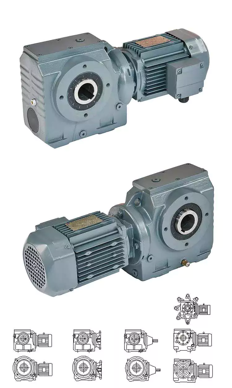 Double throat worm gear
There are a few things to consider when choosing a dual-throat worm gear. First, the diameter of the root circle must match the circle pitch of the larger gear. This measurement is usually done by measuring the distance between adjacent teeth. Alternatively, the worm’s normal module can be used. It is the value entered in the worm module dialog. In addition, the axial pitch of the worm should be equal to the pitch diameter of the circular pitch.
Double-throat worm gears are an excellent choice for heavy and heavy-duty applications. The design of this worm gear is ideal for heavy-duty applications as it provides a tighter connection between the worm and the gear. It is also more compact than other types of gear and is comparable to a fine-pitch lead screw.
The efficiency of a double-throat worm gear depends on the material of the gear and worm. Typically, gears are made of case-hardened steel, while worm gears are made of bronze or cast iron. In some cases, a combination of cast iron and bronze can be used.
The deflection of the worm shaft is also affected by the tooth parameters. Tooth height, pressure angle, and size factors all affect the deflection of the worm shaft. In addition, the number of worm threads is another important parameter that affects the deflection of the worm shaft.
Double-throat worm gears are commonly used in industrial applications where high drive reduction is required. The worm has a concave and internal tooth structure that can be adjusted to achieve various ratios. Worm gears and worm gear assemblies must be properly mounted on their shafts to prevent back drive.
Brass worm gear
The basic working principle of the brass worm gear reducer gearbox is the same as that of the traditional worm gear reducer gearbox. Its axial pitch must be equal to the circumferential pitch of the larger gear. The single-thread design advances one tooth per revolution, while the double-thread design advances two teeth. The threads on the worm are either left-handed or right-handed. The lead of a worm is the distance a point on the thread of the worm moves in one revolution. The lead angle is the angle tangent to the pitch of the cylinder and the axis of the worm.
Double-thread worm gear reducer gearboxes are best for heavy loads. It provides the tightest connection between the worm and the gear. Assembly of the worm gear requires precise mounting. The keyway installation method involves drilling a square cut in the gear hole. This prevents the worm from rotating on the shaft and helps transmit torque. Then use the set screw to secure the gear to the hub.
The large fuel tank helps keep the worm gear clean and reduces heat. It also provides lubrication for extended life. Worm gear reducer gearboxes with oil reservoirs provide a lubricated environment and low-friction surfaces. Additionally, it offers multi-position installation flexibility. Additionally, its housing is cross-milled for precise alignment. It also features internal baffles for leak-free ventilation.
I260 series worm gear reducer gearboxes are one-piece iron casings with solid or hollow output shafts and tapered roller bearings. This gear reducer gearbox is designed for low to medium-horsepower applications. This gear reducer gearbox is a cost-effective option with low initial cost, the high gear ratio, and high torque in a compact package. Also, it is more shock resistant than other gear reducer gearboxes.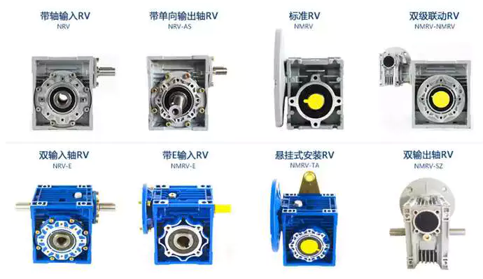 Brass worm gear
Brass worm gear reducer gearbox is a reduction gear. This type of gear can provide a lot of reduction in a small package. This type of gear reducer gearbox also has the ability to generate high torque. However, it is important to understand that this gear reducer gearbox has thermal limitations, which reduce its efficiency. The choice of lubricant for this gear reducer gearbox is very flexible. However, being a yellow metal, it is important to remember that the lubricant must be non-reactive.
Worm gears are used in many consumer and industrial applications and have high reduction ratios. These gears are produced in various configurations and sizes. Worm gears are similar to spur gears but have non-parallel shafts. Worm gears are also suitable for applications requiring low output speed but high torque.
Worm gears have some distinct advantages over other gears. First, unlike standard gears, the worm rotates in a worm-like motion. This mechanism prevents reverse movement. This is because the lead angle of the worm gear is small. Additionally, the worms self-lock, helping to prevent reversal. However, this mechanism is not entirely reliable. Worm gears can be found in elevators, fishing reels, sprockets, and automotive power steering.
Another advantage of worm gears is that they are easy to manufacture. The rationale behind this design is to have two mutually perpendicular axes. Then, two or more threads are added to the worm gear. The common tangent between these two shafts intersects the pitch line of the worm gear shaft. This is the basis of transfer speed.


editor by Cx 2023-06-20
China 1001 Round Flange Output Spur Gears High Precision Planetary Gear Reducer For Machine Tool Manufacturing worm gearbox back drive
2023-06-19
China S Series Helical Worm Gear Motor Gearbox for Agricultural Machine worm gearbox design
Merchandise Description
S series Helical Geared Motor Traits
one. Functions:
- High performance: seventy five%-eighty%
- Large technological innovation: the helical gear and a worm equipment combined with an integrated transmission to improve the torque and effectiveness.
- High precision: the equipment is manufactured of substantial-high quality alloy steel forging, carbonitriding and hardening remedy, grinding procedure to make certain high precision and stable operating.
- Higher interchangeability: hugely modular, serial layout, powerful versatility and interchangeability.
2. Technological parameters
| Ratio | 6.8-288 |
| Enter electricity | .12-22KW |
| Output torque | 11-4530N.m |
| Output speed | five-206rpm |
| Mounting kind | Foot mounted, foot mounted with CZPT shaft, output flange mounted, hollow shaft mounted, B5 flange mounted with hollow shaft, foot mounted with hollow shaft, B14 flange mounted with hollow shaft, foot mounted with splined hole, foot mounted with shrink disk, hollow shaft mounted with anti-torque arm. |
| Input Method | Flange enter(AM), shaft input(Advert), inline AC motor enter, or AQA servo motor |
| Brake Launch | HF-handbook release(lock in the brake release situation), HR-handbook launch(autom-atic braking placement) |
| Thermistor | TF(Thermistor defense PTC thermisto) TH(Thermistor protection Bimetal swotch) |
| Mounting Place | M1, M2, M3, M4, M5, M6 |
| Type | S37-S97 |
| Output shaft dis. | 20mm, 25mm, 30mm, 35mm, 40mm, 50mm, 60mm, 70mm, |
| Housing substance | HT200 substantial-toughness solid iron from R37,forty seven,fifty seven,sixty seven,seventy seven,87 |
| Housing material | HT250 Higher energy forged iron from R97 107,137,147, 157,167,187 |
| Warmth treatment technology | carbonitriding and hardening treatment method |
| Single Stage Effectiveness | 75%-80% |
| Lubricant | VG220 |
| Safety Course | IP55, F class |
About Us
ZheJiang CZPT Drive Co.,Ltd,the predecessor was a state-owned navy mould company, was recognized in 1965. CZPT specializes in the full electricity transmission solution for substantial-stop gear production industries dependent on the purpose of “Platform Solution, Software Design and Specialist Support”.
Starshine have a strong specialized force with more than 350 employees at present, including in excess of thirty engineering specialists, thirty good quality inspectors, covering an location of 80000 square CZPT and kinds of sophisticated processing equipment and testing equipments. We have a excellent basis for the market application growth and service of high-conclude speed reducers & variators owning to the provincial engineering engineering analysis center,the lab of equipment pace reducers, and the base of modern day R&D.
Our Staff
Top quality Manage
Quality:Insist on Improvement,Strive for Excellence With the development of equipment manufacturing indurstry,customer never satirsfy with the current quality of our products,on the contrary,wcreate the value of quality.
Quality policy:to enhance the overall level in the field of power transmission
Quality View:Continuous Improvement , pursuit of excellence
Quality Philosophy:Quality creates value
3. Incoming Quality Control
To establish the AQL acceptable level of incoming material control, to provide the material for the whole inspection, sampling, immunity. On the acceptance of qualified products to warehousing, substandard goods to take return, check, rework, rework inspection responsible for tracking bad, to monitor the supplier to take corrective
measures to prevent recurrence.
4. Process Quality Control
The manufacturing site of the first examination, inspection and final inspection, sampling according to the requirements of some projects, judging the quality change trend
found abnormal phenomenon of manufacturing, and supervise the production department to improve, eliminate the abnormal phenomenon or state.
5. FQC(Final QC)
After the manufacturing department will complete the product, stand in the customer’s position on the finished product quality verification, in order to ensure the quality of
customer expectations and needs.
6. OQC(Outgoing QC)
After the product sample inspection to determine the qualified, allowing storage, but when the finished product from the warehouse before the formal delivery of the goods, there is a check, this is called the shipment inspection.Check content:In the warehouse storage and transfer status to confirm, while confirming the delivery of the
solution is a product inspection to determine the qualified products.
7. Certification.
Packing
Delivery
| Application: | Machinery, Agricultural Machinery, Dumbwaiter, Sugar Mills, and Kinds of Equipments |
|---|---|
| Function: | Distribution Power, Change Drive Torque, Change Drive Direction, Speed Changing, Speed Reduction, Lower Rotation Speed |
| Layout: | Cycloidal |
| Hardness: | Hardened Tooth Surface |
| Installation: | Oscillating Base Type |
| Step: | Three-Step |
| Customization: |
Available
|
|
|---|
A-Drive PWC single worm reducer gearbox
A worm gear is a gear used to reduce the speed of a mechanical device. Often used in the automotive and shipbuilding industries, these gears have a lifespan comparable to many other types of reducer gearboxes. As a result, worm gears continue to be popular with engineers.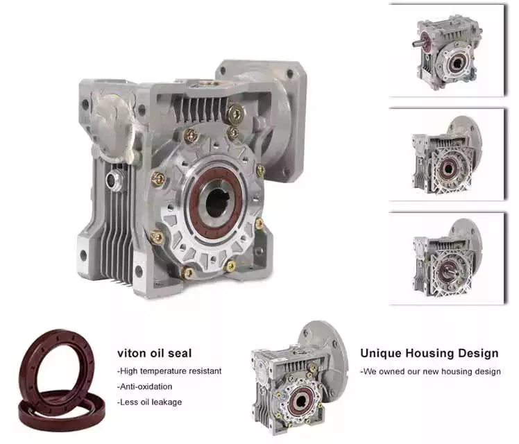
Agknx driver
Conical drive worm reducer gearboxes are an excellent choice for a variety of applications. The double-enveloping worm gear geometry of the Agknx Drive reducer gearbox provides a larger contact area and higher torque carrying capacity. This specialized gear system is also ideal for applications requiring higher precision.
Agknx Drive’s products are ideal for the solar, packaging, steel, food and pulp and paper industries. Additionally, Agknx Drive’s products are ideal for motion control and medium to heavy duty applications. The company’s dedicated sales and service teams are available to assist with your specific needs.
Agknx drive worm gear reducer gearboxes are available in single, double and triple reductions. Depending on the application, a single stage unit can transport up to 7,500 lbs. of torque. Its low-cost, compact design makes it a convenient option. Conical drive gearboxes are versatile and durable.
X & H
X & H worm gear units feature worm gear sets and are available in two different series. The X-Series includes XA versions with shaft and XF to XC versions with motor mounts. Compared to the XC compact series, the XF series offers outstanding versatility and higher efficiency. The H series combines the features of the X series with a spur gear pre-stage on the input. The H series has a die cast aluminum housing and cast iron shaft.
The X & H Worm reducer gearbox Series “H” helical gears are compatible with NMRV and C side input 56F wired motors. These gear reducer gearboxes are low cost and easy to install. They feature a cast iron housing and four threaded mounting holes.
RV seriese aluminum right angle
RV seriese aluminum right angle worm reduces versatility and durability. They are available in a variety of sizes including 25, 30, 40, 50, 63, 75, 110, 130, 150. Featuring standard NEMA motor input flanges and torque arm or foot mounting options, these reducer gearboxes are ideal for a variety of applications.
RV series worm gear reducer gearbox is made of high-quality aluminum alloy with compact structure. It also features light weight, corrosion resistance and low noise. Its housing is made of die-cast aluminum alloy, while the worm gear is made of 20CrM. The worm gear is heat treated by carbon quenching to increase its hardness. The thickness of the carbide layer is between 0.3-0.5mm.
These worm gear reducer gearboxes have multiple functions to maximize efficiency. In addition to being corrosion resistant, they are available in a variety of sizes to suit any application. Other features include a corrosion-resistant cast iron housing, enclosed breather, double-lip seal and magnetic drain plug. These worm gear reducer gearboxes are available with single or dual input shafts and are interchangeable with NMRVs.
Aluminum alloy right angle worm reducer gearbox is a light, durable and efficient gear reduction device. Its compact design makes it lighter than other gearheads, while its rust-resistant surface and long life make it an excellent choice for industrial and automotive applications. It is available in a variety of sizes, including inches.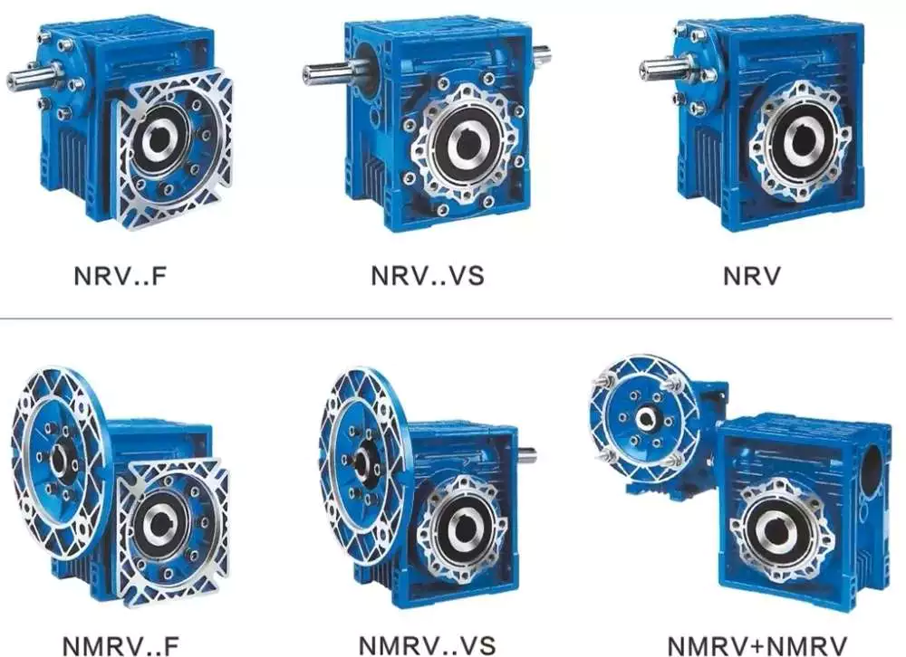 AGknx Single
Worm reducer gearboxes can be classified as sacrificial gears. It is used to reduce the torque of the machine. It has two parts: a worm and wheels. The worm can be made of brass or steel. Brass worm gears corrode easily. Phosphorus EP gear fluid can run on brass worm gears. It creates a thin oxide layer on the gear teeth, protecting them from impact forces and extreme mechanical conditions. Unfortunately, it can also cause serious damage to the brass wheels.
Worm reducer gearboxes work by transferring energy only when the worm is sliding. This process wears away the lubricating layer and metal of the wheel. Eventually, the worm surface reaches the top of the wheel and absorbs more lubricant. This process will repeat itself in the next revolution.
Worm reducer gearboxes have two benefits: they are compact and take up little space. They can slow down high-output motors while maintaining their torque. Another important feature of the worm gear reducer gearbox is its high transmission ratio capability. It can be installed in both vertical and horizontal positions, and a bidirectional version is also available.
Worm gears have some complications compared to standard gear sets, but overall they are reliable and durable. Proper installation and lubrication can make them sturdy, efficient devices.
A-Drive AGknx Single
If you’re considering purchasing a new worm gear reducer gearbox for your A-Drive AGknx single, you need to understand your goals. While single-stage worm reducer gearboxes can be used, their reduction ratios are often limited. In most cases, they can only achieve a reduction ratio of 10:1. However, there are other types of gears that provide additional speed reduction capabilities.
The worm reducer gearbox consists of two parts: the input worm and the output worm. Each component has its own rotational speed, the input worm rotates in a single direction and the output worm wheel rotates vertically. In a five-to-one ratio, the input worm rotates five times for each output worm. Likewise, a 60-to-1 ratio requires 60 revolutions of each worm. Due to this arrangement, the worm reducer gearbox is inefficient. Gear reduction is inefficient due to sliding friction rather than rolling friction.
Worm reducer gearboxes are also susceptible to thermal stress. They run hotter than hypoid reducer gearboxes, which reduces their useful life. In addition to higher heat, worm reducer gearboxes can experience component failure over time. In addition, an oil change is imminent due to the deterioration of lubrication.
The worm gear reducer gearbox of the A-Drive PPC single is a direct drive gearbox for personal watercraft. It has bronze bushings, aluminum gears, and a spool box. The spool box has a quarter-inch plated spool to wrap 1/4-inch 7 x 19 aircraft cable. Its design also makes it a more efficient alternative to belt-driven AGknx cranes. AGknx X & H
The AGknx X & H worm gear reducer gearbox series is a high-performance universal mount worm gear reducer gearbox. It features a spur gear primary on the input for higher performance and a wider range of gear ratios. Its design also allows it to be used with a variety of input shaft types, including shaft and closed-coupled applications.
It is available in a variety of sizes, including popular frame sizes 90 and 110. The worm shaft is made of case-hardened alloy steel with a cast iron hub and bronze ring gear. The standard output shaft is hollow. There are also models with dual single-shaft outputs.


editor by CX 2023-04-21
China Hot Sale Quality Machine Gear Box Casting Cast Irom Gearbox Reducer For Driving Motion brushless dc motor worm gearbox
Warranty: 1 a long time
Relevant Industries: Constructing Substance Outlets
Weight (KG): 3 KG
Personalized assist: OEM
Gearing Arrangement: Worm
Output Torque: 1.8-2430N.M
Input Speed: 1400RPM
Output Velocity: 19-186.7RPM
Producing method of equipment: Solid equipment
Toothed Part Shape: Involute spur gear
Colour: silver, blue, black and so on
key word: gearbox WPA
Packaging Details: interior pack: use plastic bag and foam box,gearbox WPA . outer pack: carton or wood circumstance for every established or dependent on customer’s request.
one.Housing:iron cast2. reduced noise(<50DB)3.Model:WPA forty-250,Ratio:10 to 604.Efficient and risk-free operating5.ISO9001,Factory price,OEM6.Technologies Info:
| Type: | gearbox WPA |
| Model: | WPA 40-250 |
| Ratio: | 1:10,fifteen,20,twenty five,thirty,40,50,sixty |
| Color: | Blue/Silver Or On Buyer Request |
| Material: | Housing: Die-Solid Iron solid |
| Worm Equipment-Copper-10-3# | |
| Worm-20CrMn Ti with carburizing and quenching, area harness is 56-62HRC | |
| Shaft-chromium steel-45# | |
| Packing: | Carton and Wooden Circumstance |
| Bearing: | C&U Bearing |
| Seal: | NAK OTHER |
| Warranty: | 1 Calendar year |
| Input Electrical power: | 0.06KW,.09KW |
| Usages: | Industrial Equipment: Food Stuff, Ceramics,CHEMICAL,Packing,Dyeing,Woodworking,Glass. |
| IEC Flange: | 56B14, 63B14, 63B5, 63B5, 71B14,80B14 AND SO ON |
| Lubricant: | Synthetic&Mineral |
Worm gear reducer
Cheaper than planetary gearboxes In many cases, worm gear reducers are a popular alternative to planetary gearboxes. A worm gear reducer is a mechanical device with vertical input and output shafts. This allows for very high reduction ratios. They are typically used in high-reduction situations such as machine tools.
Worm gears are cheaper than traditional gearboxes. They also have many benefits, including noise reduction. The output shaft of the worm gear reducer is almost 90 degrees from the motor input shaft, making it ideal for high-torque applications.
The worm gear reducer adopts an aluminum body, which is light in weight and high in operation efficiency. Additionally, they are available with hollow shafts and mounting flanges. In terms of initial cost, worm gear reducers are cheaper than planetary gearboxes. In addition, they have better efficiency and longer service life.
Worm drives are also ideal for portable battery-powered lifting equipment. The high gear ratio of the worm gear ensures that it does not reverse drive. The worm gear has a spring-applied brake that holds the motor in place.
Planetary gearboxes are popular among industrial users. The efficiency of planetary gearboxes is important for practical applications.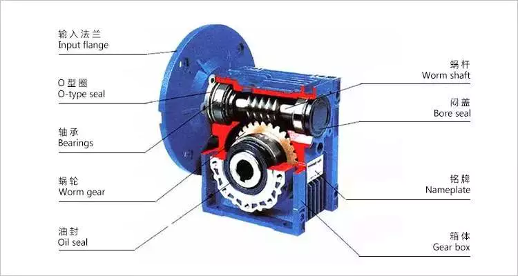
The compact worm gear unit consists of a housing with an inner cavity. It has two side walls, one on either side of the front cover (13) and one on both sides of the rear cover (14). The front end cap is screwed onto the housing and the inner cavity is accessed through the rear end cap.
The compact worm gear unit can be configured to suit your application. They have many advantages, including saving space and increasing torque. The range includes single-envelope and double-envelope versions, available in a number of different power ratings. Additionally, they are IP65-rated, making them ideal for applications involving high radial or axial forces.
The compact worm reducer is a simple but effective worm drive. Its worm gear 16 meshes with the output shaft and rotates relatively stably. It also has a front-end cap and rear bearing. This enables the compact worm reducer to reduce vibration without damaging the output shaft.
Compact worm gear reducers are ideal for many applications and offer high efficiency. The compact design means you can mount them on the motor’s flange or base. Its durable construction makes it ideal for a variety of industries. They are extremely durable and can handle high-pressure and washdown conditions. They also come standard with a synthetic shaft.
high efficiency
High-efficiency worm gear reducers are ideal for applications that require precision, repeatability, and efficient performance. These reducers are designed with state-of-the-art servo motor technology to provide tight integration and an angular backlash of less than two arc minutes. The reduction ratio can be lower if the application requires it.
Rising energy costs have led to an increased focus on the efficiency of drives. In response to this, manufacturers have increased the efficiency of worm gear reducers through a number of technical improvements. By minimizing losses from rolling and sliding friction, worm gear reducers are more efficient than their counterparts.
The high-efficiency worm reducer is simple in design and has the characteristics of a compact structure, high-speed ratio, low power consumption, and self-locking. Other advantages of these reducers include low noise and long service life. Many also have built-in control systems that allow manual and remote adjustments. They also feature automatic shutdown protection and thermal protection.
High-efficiency worm reducers can be used for mechanical acceleration. The input hypoid gear is usually made of steel, while the output hypoid gear is usually made of bronze. Bronze is a soft metal that is good at absorbing shock loads. However, bronze requires work hardening to achieve optimum hardness. For large worm gears, this process can take 300 to 550 hours.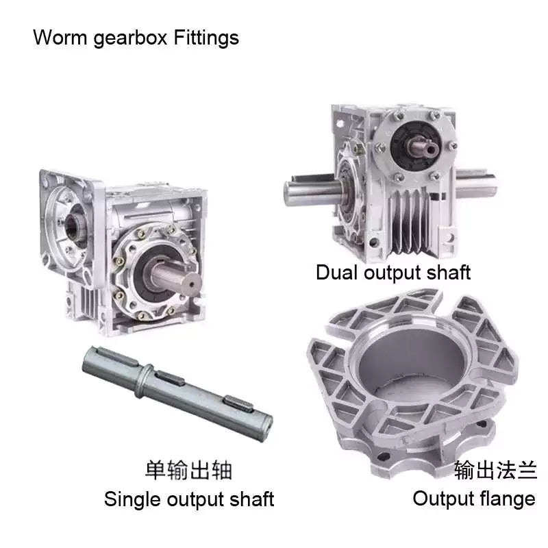
low clearance
A low-clearance worm reducer is a device used to adjust the speed of a rotating shaft. It uses a worm gear consisting of two members. One worm is at one end of the shaft and the other is at the other end. Both worms are screwed into the synchronous drive structure.
Low clearance worm gear reducers can be produced on conventional worm gear production lines without overlapping investments. These units are usually made of soft rubber. Also, they are relatively quiet in operation. These machines are designed so that they are suitable for use in elevators. The softer material in the worm gear also helps absorb shock loads.
The tooth profile of the worm gear is designed to change with the axial movement of the worm. Worms have thinner right teeth and thicker left teeth. As the worm moves to the right, its teeth mesh with the worm gear, reducing backlash.
There are many different types of worm gears. The design of gears depends on many factors, including backlash, thermal design, friction factors and lubrication. Worm gears are made of several different materials. Some different types of materials used in worm gears require special lubrication.
quieter
The quieter worm reducer is designed to reduce the noise level of the rotating gear motor. The device has more gear teeth in meshing contact with the gears, which helps it run more quietly. In addition to being quieter than other transmissions, it’s also less expensive than its counterparts.
Worm gearboxes can be used for different applications, but they are not as efficient as helical gearboxes. Worm reducers are cheaper but less than 90% efficient. Higher gear ratios reduce efficiency, so worm gear reducers are better suited for applications that require low-speed torque. The cost of buying a worm gearbox will depend on the horsepower and gear ratios required.
Worm reducers are also more comfortable to use than planetary gearboxes. They don’t vibrate and heat up quickly, making them an excellent choice for low to medium horsepower applications. Worm gear reducers can be upgraded to improve their performance by combining with other gear trains or gearboxes.
easy to replace
An easily replaceable worm gear reducer can save you a lot of money. A worm gear reducer is part of a chain drive and allows you to change gear ratios quickly and easily. Worm gear reducers can be easily replaced in a number of ways. It’s a good idea to read the manufacturer’s manual before replacing a worm gear reducer. Make sure you have the instructions available so you can refer to them in the future.
Worm gear reducers offer many advantages, including long service life and low noise. They are also designed with a 90-degree output shaft for easy installation. Another advantage of these gear reducers is that they can be used with both solid and hollow output shafts. This means less maintenance and downtime.
Worm gear reducers are widely used. Most gear manufacturers have large inventories. Worm gears also have uniform mounting dimensions. Dimensional consistency means you don’t have to worry about matching the shaft length and diameter to the worm gear. You can easily find a replacement worm gear reducer for your equipment.
When replacing the worm gear reducer, check the lubricating oil recommended by the machine. If not included, use original gear oil. Be sure to follow the manufacturer’s instructions carefully.


editor by czh
China Custom Gearbox Motor Machine for Elevators HW135L GEM Made in Italy Traction Machine Motor with external support with Hot selling
Warranty: 3 several years
Relevant Industries: Creating Material Shops, Lifts and elevators
Tailored support: sure
Gearing Arrangement: Worm
Output Torque: 950 – 1.094 N/m
Output Speed: ,5 – 1,2 m/s
Cabin speed until finally 1,2m/s, special 3VF: Can be very easily dis-assembled for easy transportation and installation
With solitary-stage 230V-50Hz fan: With exterior help for bigger static load
A few factors of fixation: No particular tools required for routine maintenance
Option customised emblem and shade: No Sound: considerably less than sixty Db (complying with IEC 39-4 CEI EN 60034-9),
a hundred% Italian solution, 100% Created in Italy: one hundred% Italian manufacturing by Italian skilled professionals
No manufacturing services exterior Italy: 100% Italian House
GEM ITALY: Gearbox developed for VVVF travel
Certification: EN 81
Packaging Details: Gearbox on pallet or inside wood box
Port: Any in Northern Italy
Specification
| item | value |
| Warranty | 3 years |
| Certification | EN 81 |
| Applicable Industries | Building Content Outlets, Lifts and elevators |
| Customized assist | yes |
| Place of Origin | Italy |
| Brand Identify | GEM |
| Gearing Arrangement | Worm |
| Output Torque | 950 – 1.094 N/m |
| Output Speed | 0,5 – 1,2 m/s |
| Cabin velocity until finally 1,2m/s, specific 3VF | Can be very easily dis-assembled for simple transport and installation |
| With one-stage 230V-50Hz admirer | With exterior assistance for greater static load |
| Three details of fixation | No specific tools required for upkeep |
| Option customised symbol and color | No Sounds: considerably less than sixty Db (complying with IEC 39-4 CEI EN 60034-9), |
| 100% Italian product, 100% Made in Italy | 100% Italian manufacturing by Italian competent professionals |
| No creation facilities exterior Italy | 100% Italian House |
| GEM ITALY | Gearbox made for VVVF generate |
What Is a Gearbox?
There are several factors to consider when choosing a gearbox. Backlash, for example, is a consideration, as it is the angle at which the output shaft can rotate without the input shaft moving. While this isn’t necessary in applications without load reversals, it is important for precision applications involving load reversals. Examples of these applications include automation and robotics. If backlash is a concern, you may want to look at other factors, such as the number of teeth in each gear.
Function of a gearbox
A gearbox is a mechanical unit that consists of a chain or set of gears. The gears are mounted on a shaft and are supported by rolling element bearings. These devices alter the speed or torque of the machine they are used in. Gearboxes can be used for a wide variety of applications. Here are some examples of how gearboxes function. Read on to discover more about the gears that make up a gearbox.
Regardless of the type of transmission, most gearboxes are equipped with a secondary gear and a primary one. While the gear ratios are the same for both the primary and secondary transmission, the gearboxes may differ in size and efficiency. High-performance racing cars typically employ a gearbox with two green and one blue gear. Gearboxes are often mounted in the front or rear of the engine.
The primary function of a gearbox is to transfer torque from one shaft to another. The ratio of the driving gear’s teeth to the receiving member determines how much torque is transmitted. A large gear ratio will cause the main shaft to revolve at a slower speed and have a high torque compared to its counter shaft. Conversely, a low gear ratio will allow the vehicle to turn at a lower speed and produce a lower torque.
A conventional gearbox has input and output gears. The countershaft is connected to a universal shaft. The input and output gears are arranged to match the speed and torque of each other. The gear ratio determines how fast a car can go and how much torque it can generate. Most conventional transmissions use four gear ratios, with one reverse gear. Some have two shafts and three inputs. However, if the gear ratios are high, the engine will experience a loss of torque.
In the study of gearbox performance, a large amount of data has been collected. A highly ambitious segmentation process has yielded nearly 20,000 feature vectors. These results are the most detailed and comprehensive of all the available data. This research has a dual curse – the first is the large volume of data collected for the purpose of characterization, while the second is the high dimensionality. The latter is a complication that arises when the experimental gearbox is not designed to perform well.
Bzvacklash
The main function of a gearhead is to multiply a moment of force and create a mechanical advantage. However, backlash can cause a variety of issues for the system, including impaired positioning accuracy and lowered overall performance. A zero backlash gearbox can eliminate motion losses caused by backlash and improve overall system performance. Here are some common problems associated with backlash in gearheads and how to fix them. After you understand how to fix gearbox backlash, you’ll be able to design a machine that meets your requirements.
To reduce gearbox backlash, many designers try to decrease the center distance of the gears. This eliminates space for lubrication and promotes excessive tooth mesh, which leads to premature mesh failure. To minimize gearbox backlash, a gear manufacturer may separate the two parts of the gear and adjust the mesh center distance between them. To do this, rotate one gear with respect to the fixed gear, while adjusting the other gear’s effective tooth thickness.
Several manufacturing processes may introduce errors, and reducing tooth thickness will minimize this error. Gears with bevel teeth are a prime example of this. This type of gear features a small number of teeth in comparison to its mating gear. In addition to reducing tooth thickness, bevel gears also reduce backlash. While bevel gears have fewer teeth than their mating gear, all of their backlash allowance is applied to the larger gear.
A gear’s backlash can affect the efficiency of a gearbox. In an ideal gear, the backlash is zero. But if there is too much, backlash can cause damage to the gears and cause it to malfunction. Therefore, the goal of gearbox backlash is to minimize this problem. However, this may require the use of a micrometer. To determine how much gearbox backlash you need, you can use a dial gauge or feeler gauge.
If you’ve been looking for a way to reduce backlash, a gearbox’s backlash may be the answer. However, backlash is not a revolt against the manufacturer. It is an error in motion that occurs naturally in gear systems that change direction. If it is left unaccounted for, it can lead to major gear degradation and even compromise the entire system. In this article, we’ll explain how backlash affects gears and how it affects the performance of a gearbox.
Design
The design of gearboxes consists of a variety of factors, including the type of material used, power requirements, speed and reduction ratio, and the application for which the unit is intended. The process of designing a gearbox usually begins with a description of the machine or gearbox and its intended use. Other key parameters to consider during gearbox design include the size and weight of the gear, its overall gear ratio and number of reductions, as well as the lubrication methods used.
During the design process, the customer and supplier will participate in various design reviews. These include concept or initial design review, manufacturing design validation, critical design review, and final design review. The customer may also initiate the process by initiating a DFMEA. After receiving the initial design approval, the design will go through several iterations before the finalized design is frozen. In some cases, the customer will require a DFMEA of the gearbox.
The speed increaser gearboxes also require special design considerations. These gearboxes typically operate at high speeds, causing problems with gear dynamics. Furthermore, the high speeds of the unit increase frictional and drag forces. A proper design of this component should minimize the effect of these forces. To solve these problems, a gearbox should incorporate a brake system. In some cases, an external force may also increase frictional forces.
Various types of gear arrangements are used in gearboxes. The design of the teeth of the gears plays a significant role in defining the type of gear arrangement in the gearbox. Spur gear is an example of a gear arrangement, which has teeth that run parallel to the axis of rotation. These gears offer high gear ratios and are often used in multiple stages. So, it is possible to create a gearbox that meets the needs of your application.
The design of gearboxes is the most complex process in the engineering process. These complex devices are made of multiple types of gears and are mounted on shafts. They are supported by rolling element bearings and are used for a variety of applications. In general, a gearbox is used to reduce speed and torque and change direction. Gearboxes are commonly used in motor vehicles, but can also be found in pedal bicycles and fixed machines.
Manufacturers
There are several major segments in the gearbox market, including industrial, mining, and automotive. Gearbox manufacturers are required to understand the application and user industries to design a gearbox that meets their specific requirements. Basic knowledge of metallurgy is necessary. Multinational companies also provide gearbox solutions for the power generation industry, shipping industry, and automotive industries. To make their products more competitive, they need to focus on product innovation, geographical expansion, and customer retention.
The CZPT Group started as a small company in 1976. Since then, it has become a global reference in mechanical transmissions. Its production range includes gears, reduction gearboxes, and geared motors. The company was the first in Italy to achieve ISO certification, and it continues to grow into one of the world’s leading manufacturers of production gearboxes. As the industry evolves, CZPT focuses on research and development to create better products.
The agriculture industry uses gearboxes to implement a variety of processes. They are used in tractors, pumps, and agricultural machinery. The automotive industry uses gears in automobiles, but they are also found in mining and tea processing machinery. Industrial gearboxes also play an important role in feed and speed drives. The gearbox industry has a diverse portfolio of manufacturers and suppliers. Here are some examples of gearboxes:
Gearboxes are complex pieces of equipment. They must be used properly to optimize efficiency and extend their lifespan. Manufacturers employ advanced technology and strict quality control processes to ensure their products meet the highest standards. In addition to manufacturing precision and reliability, gearbox manufacturers ensure that their products are safe for use in the production of industrial machinery. They are also used in office machines and medical equipment. However, the automotive gearbox market is becoming increasingly competitive.

