Tag Archives: gear motor reducer

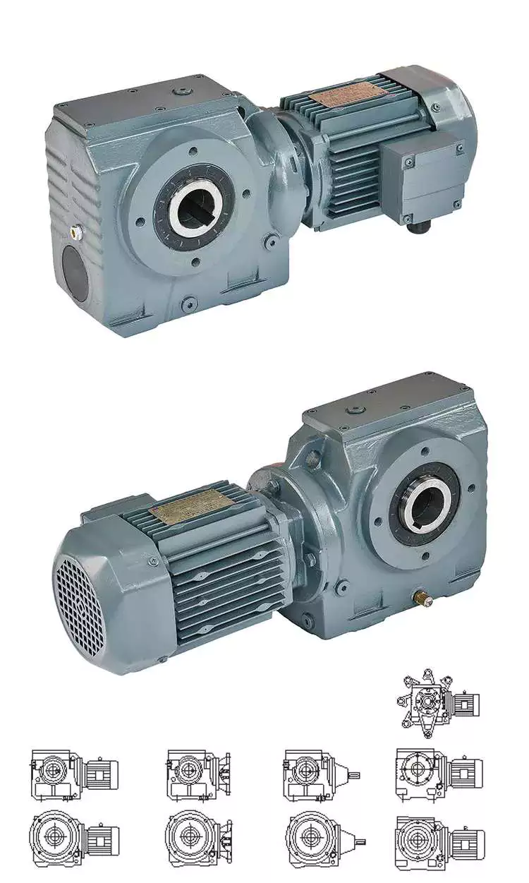
China Hot Sale Quality Machine Gear Box Casting Cast Irom Gearbox Reducer For Driving Motion brushless dc motor worm gearbox

Warranty: 1 a long time
Relevant Industries: Constructing Substance Outlets
Weight (KG): 3 KG
Personalized assist: OEM
Gearing Arrangement: Worm
Output Torque: 1.8-2430N.M
Input Speed: 1400RPM
Output Velocity: 19-186.7RPM
Producing method of equipment: Solid equipment
Toothed Part Shape: Involute spur gear
Colour: silver, blue, black and so on
key word: gearbox WPA
Packaging Details: interior pack: use plastic bag and foam box,gearbox WPA . outer pack: carton or wood circumstance for every established or dependent on customer’s request.

one.Housing:iron cast2. reduced noise(<50DB)3.Model:WPA forty-250,Ratio:10 to 604.Efficient and risk-free operating5.ISO9001,Factory price,OEM6.Technologies Info:

Type:gearbox WPA
Model:WPA 40-250
Ratio:1:10,fifteen,20,twenty five,thirty,40,50,sixty
Color:Blue/Silver Or On Buyer Request
Material:Housing: Die-Solid Iron solid
Worm Equipment-Copper-10-3#
Worm-20CrMn Ti with carburizing and quenching, area harness is 56-62HRC
Shaft-chromium steel-45#
Packing:Carton and Wooden Circumstance
Bearing:C&U Bearing
Seal:NAK OTHER
Warranty:1 Calendar year
Input Electrical power:0.06KW,.09KW
Usages:Industrial Equipment: Food Stuff, Ceramics,CHEMICAL,Packing,Dyeing,Woodworking,Glass.
IEC Flange:56B14, 63B14, 63B5, 63B5, 71B14,80B14 AND SO ON
Lubricant:Synthetic&Mineral
Item Classification Solution Big difference About Us Exhibition Certification Packing&Shipping and delivery FAQ 1.Q:What information need to i tell you to verify the worm gearbox?A:Product/Dimensions,B:Ratio and output torque, C:Powe and flange type,D:Shaft Path,E:Housing colour,F:Order amount.2.What variety of payment approaches do you settle for?A:T/T,B:B/L,C:Money 3.What is actually your guarantee?1 yr. 4.How to shipping?A:By sea- Buyer appoints forwarder,or our income crew finds suited forwarder for customers.By air- Customer gives acquire convey account,or our income team fingds ideal convey for customers.(Mostly for sample) Other- We prepare to supply items to some spot in China appointed by buyers. 5.Can you make OEM/ODM get?Sure,we have abundant expertise on OEM/ODM buy and like indication Non-disclosure Arrangement just before sample making

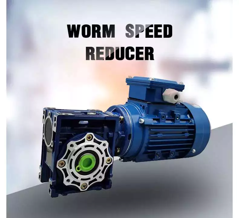
Worm gear reducer

Cheaper than planetary gearboxes In many cases, worm gear reducers are a popular alternative to planetary gearboxes. A worm gear reducer is a mechanical device with vertical input and output shafts. This allows for very high reduction ratios. They are typically used in high-reduction situations such as machine tools.
Worm gears are cheaper than traditional gearboxes. They also have many benefits, including noise reduction. The output shaft of the worm gear reducer is almost 90 degrees from the motor input shaft, making it ideal for high-torque applications.
The worm gear reducer adopts an aluminum body, which is light in weight and high in operation efficiency. Additionally, they are available with hollow shafts and mounting flanges. In terms of initial cost, worm gear reducers are cheaper than planetary gearboxes. In addition, they have better efficiency and longer service life.
Worm drives are also ideal for portable battery-powered lifting equipment. The high gear ratio of the worm gear ensures that it does not reverse drive. The worm gear has a spring-applied brake that holds the motor in place.
Planetary gearboxes are popular among industrial users. The efficiency of planetary gearboxes is important for practical applications.
worm_reducer

pocket

The compact worm gear unit consists of a housing with an inner cavity. It has two side walls, one on either side of the front cover (13) and one on both sides of the rear cover (14). The front end cap is screwed onto the housing and the inner cavity is accessed through the rear end cap.
The compact worm gear unit can be configured to suit your application. They have many advantages, including saving space and increasing torque. The range includes single-envelope and double-envelope versions, available in a number of different power ratings. Additionally, they are IP65-rated, making them ideal for applications involving high radial or axial forces.
The compact worm reducer is a simple but effective worm drive. Its worm gear 16 meshes with the output shaft and rotates relatively stably. It also has a front-end cap and rear bearing. This enables the compact worm reducer to reduce vibration without damaging the output shaft.
Compact worm gear reducers are ideal for many applications and offer high efficiency. The compact design means you can mount them on the motor’s flange or base. Its durable construction makes it ideal for a variety of industries. They are extremely durable and can handle high-pressure and washdown conditions. They also come standard with a synthetic shaft.

high efficiency

High-efficiency worm gear reducers are ideal for applications that require precision, repeatability, and efficient performance. These reducers are designed with state-of-the-art servo motor technology to provide tight integration and an angular backlash of less than two arc minutes. The reduction ratio can be lower if the application requires it.
Rising energy costs have led to an increased focus on the efficiency of drives. In response to this, manufacturers have increased the efficiency of worm gear reducers through a number of technical improvements. By minimizing losses from rolling and sliding friction, worm gear reducers are more efficient than their counterparts.
The high-efficiency worm reducer is simple in design and has the characteristics of a compact structure, high-speed ratio, low power consumption, and self-locking. Other advantages of these reducers include low noise and long service life. Many also have built-in control systems that allow manual and remote adjustments. They also feature automatic shutdown protection and thermal protection.
High-efficiency worm reducers can be used for mechanical acceleration. The input hypoid gear is usually made of steel, while the output hypoid gear is usually made of bronze. Bronze is a soft metal that is good at absorbing shock loads. However, bronze requires work hardening to achieve optimum hardness. For large worm gears, this process can take 300 to 550 hours.
worm_reducer

low clearance

A low-clearance worm reducer is a device used to adjust the speed of a rotating shaft. It uses a worm gear consisting of two members. One worm is at one end of the shaft and the other is at the other end. Both worms are screwed into the synchronous drive structure.
Low clearance worm gear reducers can be produced on conventional worm gear production lines without overlapping investments. These units are usually made of soft rubber. Also, they are relatively quiet in operation. These machines are designed so that they are suitable for use in elevators. The softer material in the worm gear also helps absorb shock loads.
The tooth profile of the worm gear is designed to change with the axial movement of the worm. Worms have thinner right teeth and thicker left teeth. As the worm moves to the right, its teeth mesh with the worm gear, reducing backlash.
There are many different types of worm gears. The design of gears depends on many factors, including backlash, thermal design, friction factors and lubrication. Worm gears are made of several different materials. Some different types of materials used in worm gears require special lubrication.

quieter

The quieter worm reducer is designed to reduce the noise level of the rotating gear motor. The device has more gear teeth in meshing contact with the gears, which helps it run more quietly. In addition to being quieter than other transmissions, it’s also less expensive than its counterparts.
Worm gearboxes can be used for different applications, but they are not as efficient as helical gearboxes. Worm reducers are cheaper but less than 90% efficient. Higher gear ratios reduce efficiency, so worm gear reducers are better suited for applications that require low-speed torque. The cost of buying a worm gearbox will depend on the horsepower and gear ratios required.
Worm reducers are also more comfortable to use than planetary gearboxes. They don’t vibrate and heat up quickly, making them an excellent choice for low to medium horsepower applications. Worm gear reducers can be upgraded to improve their performance by combining with other gear trains or gearboxes.
worm_reducer

easy to replace

An easily replaceable worm gear reducer can save you a lot of money. A worm gear reducer is part of a chain drive and allows you to change gear ratios quickly and easily. Worm gear reducers can be easily replaced in a number of ways. It’s a good idea to read the manufacturer’s manual before replacing a worm gear reducer. Make sure you have the instructions available so you can refer to them in the future.
Worm gear reducers offer many advantages, including long service life and low noise. They are also designed with a 90-degree output shaft for easy installation. Another advantage of these gear reducers is that they can be used with both solid and hollow output shafts. This means less maintenance and downtime.
Worm gear reducers are widely used. Most gear manufacturers have large inventories. Worm gears also have uniform mounting dimensions. Dimensional consistency means you don’t have to worry about matching the shaft length and diameter to the worm gear. You can easily find a replacement worm gear reducer for your equipment.
When replacing the worm gear reducer, check the lubricating oil recommended by the machine. If not included, use original gear oil. Be sure to follow the manufacturer’s instructions carefully.

China Hot Sale Quality Machine Gear Box Casting Cast Irom Gearbox Reducer For Driving Motion     brushless dc motor worm gearboxChina Hot Sale Quality Machine Gear Box Casting Cast Irom Gearbox Reducer For Driving Motion     brushless dc motor worm gearbox
editor by czh

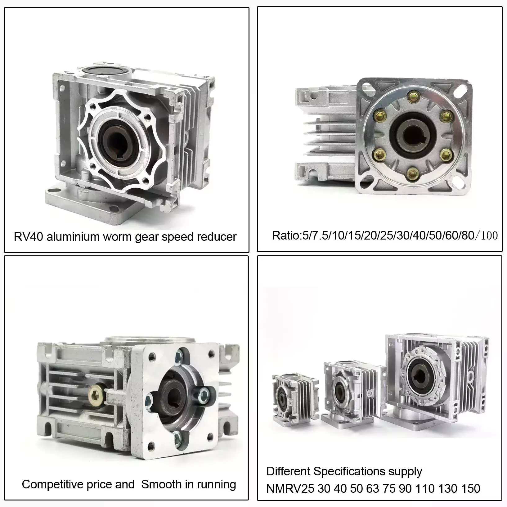
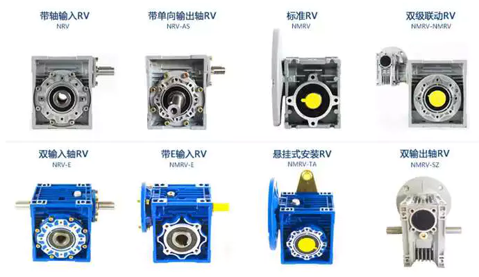
China Aluminum&Iron casting Electric Motor Gear Speed Reducer NMRV050 with Hot selling

Warranty: 1 calendar year
Relevant Industries: Manufacturing Plant, Machinery Mend Stores, Foodstuff & Beverage Manufacturing facility, Farms, Building works , Energy & Mining, Other
Custom-made assist: OEM, ODM
Gearing Arrangement: Worm
Output Torque: 2.6-1195N.m
Enter Velocity: 1400 rpm
Output Pace: fourteen-280rpm
Item title: Worm Equipment Reducer
Shade: Blue/Silver or on customer request
Material: Aluminum alloy and casting iron
Application: Equipment Resource
Certification: IECEE
Packaging Details: Interior packing: carton Outer packing: Plywood circumstance
Port: ZheJiang OR HangZhou

Material Building
Worm equipmentInternal facet:nodular cast iron QT500
Outter facet:9-4 bronze
Worm shaft20 Cr metal with carburizing method to make it more difficult
Hardening degree:surfaceHRC56-62
interiorHB220 to 260
Carburizing depth:0.3mm to .5mm
HousingADC12 aluminium alloy for WXRV30-WXRV090
HT200 forged iron for WXRV110-WXRV130
BearingHCH bearing
Oil sealSKF seal for input
NAK seal for output
OilArtificial or mineral


International exhibition
Company Info
HangZhou Wanxing reducer Co.,Ltd is set up in 1999 and is a skilled producer and supplier of NMRV,VF,WP,PLANETARY gearbox/reducer. It is positioned in HangZhou Metropolis of China,with simple obtain to air port and sea port.
Our business move the ISO9001:2000 certification. “WANGXING” brand products have been commonly employed in sectors of enviromental engineering,printing & chemical industry,logistics.beer ect. In get to boost our products high quality,we have recognized the research and growth office with knowledgeable experts.

Packaging & Delivery Basic safety Packing Method 1.Inside of :Plastic bags with Chemical Desiccant For Gearboxes/Pace Reducer 2.Center :Specific Carton packaging For Gearboxes/ Velocity Reducer 3. Exterior :Picket Box For Gearboxes/ Pace Reducer

FAQ

FAQ:

one. Q: What is type of your organization. A: We are maker.2. Q: what should I supply when I choose gearbox/velocity reducer? A: 1) load situation 2) speed of rotation or speed ratio(combination with combine speed reducer can get additional low out putting rotational pace) 3) function circumstance(temperature, humidity,corrosion and many others.) 4) area of installation3. Q: How lengthy dose it take to complete my get? A: It depends on your amount. Normally 25days for 1 20GP, 35days for 1 40HQ.4. Q: How can i know the method of my purchase? A: Thorough photo of the generation approach will be sent to you to confirm prior to transport. Consummation QC system makes it attainable to provide you reputable quality

What is a worm gear reducer?

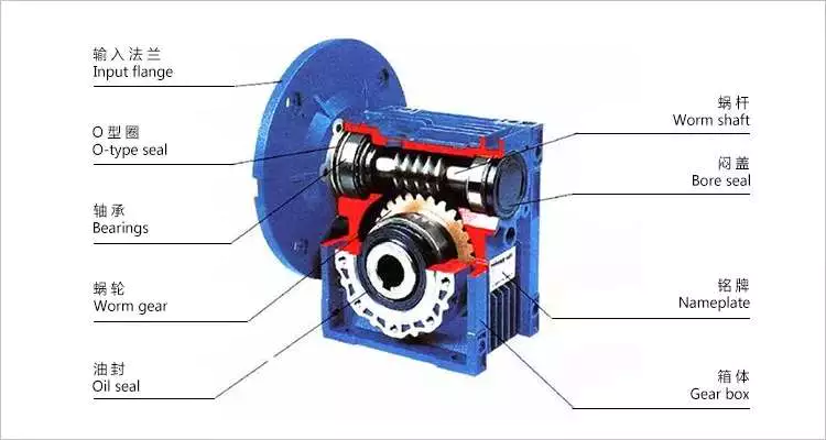
A worm gear reducer is a mechanical device that uses a worm gear and a worm to reduce the speed of a rotating shaft. The gear reducer can increase the output torque of the engine according to the gear ratio. This type of gear reducer is characterized by its flexibility and compact size. It also increases the strength and efficiency of the drive.
worm_reducer

Hollow shaft worm gear reducer

The hollow shaft worm gear reducer is an additional output shaft connecting various motors and other gearboxes. They can be installed horizontally or vertically. Depending on size and scale, they can be used with gearboxes from 4GN to 5GX.
Worm gear reducers are usually used in combination with helical gear reducers. The latter is mounted on the input side of the worm gear reducer and is a great way to reduce the speed of high output motors. The gear reducer has high efficiency, low speed operation, low noise, low vibration and low energy consumption.
Worm gear reducers are made of hard steel or non-ferrous metals, increasing their efficiency. However, gears are not indestructible, and failure to keep running can cause the gear oil to rust or emulsify. This is due to moisture condensation that occurs during the operation and shutdown of the reducer. The assembly process and quality of the bearing are important factors to prevent condensation.
Hollow shaft worm gear reducers can be used in a variety of applications. They are commonly used in machine tools, variable speed drives and automotive applications. However, they are not suitable for continuous operation. If you plan to use a hollow shaft worm gear reducer, be sure to choose the correct one according to your requirements.

Double throat worm gear

Worm gear reducers use a worm gear as the input gear. An electric motor or sprocket drives the worm, which is supported by anti-friction roller bearings. Worm gears are prone to wear due to the high friction in the gear teeth. This leads to corrosion of the confinement surfaces of the gears.
The pitch diameter and working depth of the worm gear are important. The pitch circle diameter is the diameter of the imaginary circle in which the worm and the gear mesh. Working depth is the maximum amount of worm thread that extends into the backlash. Throat diameter is the diameter of the circle at the lowest point of the worm gear face.
When the friction angle between the worm and the gear exceeds the lead angle of the worm, the worm gear is self-locking. This feature is useful for lifting equipment, but may be detrimental to systems that require reverse sensitivity. In these systems, the self-locking ability of the gears is a key limitation.
The double throat worm gear provides the tightest connection between the worm and the gear. The worm gear must be installed correctly to ensure maximum efficiency. One way to install the worm gear assembly is through a keyway. The keyway prevents the shaft from rotating, which is critical for transmitting torque. Then attach the gear to the hub using the set screw.
The axial and circumferential pitch of the worm gear should match the pitch diameter of the larger gear. Single-throat worm gears are single-threaded, and double-throat worm gears are double-throat. A single thread design advances one tooth, while a double thread design advances two teeth. The number of threads should match the number of mating gears.
worm_reducer

Self-locking function

One of the most prominent features of a worm reducer is its self-locking function, which prevents the input and output shafts from being interchanged. The self-locking function is ideal for industrial applications where large gear reduction ratios are required without enlarging the gear box.
The self-locking function of a worm reducer can be achieved by choosing the right type of worm gear. However, it should be noted that this feature is not available in all types of worm gear reducers. Worm gears are self-locking only when a specific speed ratio is reached. When the speed ratio is too small, the self-locking function will not work effectively.
Self-locking status of a worm reducer is determined by the lead, pressure, and coefficient of friction. In the early twentieth century, cars had a tendency to pull the steering toward the side with a flat tire. A worm drive reduced this tendency by reducing frictional forces and transmitting steering force to the wheel, which aids in steering and reduces wear and tear.
A self-locking worm reducer is a simple-machine with low mechanical efficiency. It is self-locking when the work at one end is greater than the work at the other. If the mechanical efficiency of a worm reducer is less than 50%, the friction will result in losses. In addition, the self-locking function is not applicable when the drive is reversed. This characteristic makes self-locking worm gears ideal for hoisting and lowering applications.
Another feature of a worm reducer is its ability to reduce axially. Worm gears can be double-lead or single-lead, and it is possible to adjust their backlash to compensate for tooth wear.

Heat generated by worm gears

Worm gears generate considerable amounts of heat. It is essential to reduce this heat to improve the performance of the gears. This heat can be mitigated by designing the worms with smoother surfaces. In general, the speed at which worm gears mesh should be in the range of 20 to 24 rms.
There are many approaches for calculating worm gear efficiency. However, no other approach uses an automatic approach to building the thermal network. The other methods either abstractly investigate the gearbox as an isothermal system or build the TNM statically. This paper describes a new method for automatically calculating heat balance and efficiency for worm gears.
Heat generated by worm gears is a significant source of power loss. Worm gears are typically characterized by high sliding speeds in their tooth contacts, which causes high frictional heat and increased thermal stresses. As a result, accurate calculations are necessary to ensure optimal operation. In order to determine the efficiency of a gearbox system, manufacturers often use the simulation program WTplus to calculate heat loss and efficiency. The heat balance calculation is achieved by adding the no-load and load-dependent power losses of the gearbox.
Worm gears require a special type of lubricant. A synthetic oil that is non-magnetic and has a low friction coefficient is used. However, the oil is only one of the options for lubricating worm gears. In order to extend the life of worm gears, you should also consider adding a natural additive to the lubricant.
Worm gears can have a very high reduction ratio. They can achieve massive reductions with little effort, compared to conventional gearsets which require multiple reductions. Worm gears also have fewer moving parts and places for failure than conventional gears. One disadvantage of worm gears is that they are not reversible, which limits their efficiency.
worm_reducer

Size of worm gear reducer

Worm gear reducers can be used to decrease the speed of a rotating shaft. They are usually designed with two shafts at right angles. The worm wheel acts as both the pinion and rack. The central cross section forms the boundary between the advancing and receding sides of the worm gear.
The output gear of a worm gear reducer has a small diameter compared to the input gear. This allows for low-speed operation while producing a high-torque output. This makes worm gear reducers great for space-saving applications. They also have low initial costs.
Worm gear reducers are one of the most popular types of speed reducers. They can be small and powerful and are often used in power transmission systems. These units can be used in elevators, conveyor belts, security gates, and medical equipment. Worm gearing is often found in small and large sized machines.
Worm gears can also be adjusted. A dual-lead worm gear has a different lead on the left and right tooth surfaces. This allows for axial movement of the worm and can also be adjusted to reduce backlash. A backlash adjustment may be necessary as the worm wears down. In some cases, this backlash can be adjusted by adjusting the center distance between the worm gear.
The size of worm gear reducer depends on its function. For example, if the worm gear is used to reduce the speed of an automobile, it should be a model that can be installed in a small car.

China Aluminum&Iron casting Electric Motor Gear Speed Reducer NMRV050     with Hot selling		China Aluminum&Iron casting Electric Motor Gear Speed Reducer NMRV050     with Hot selling
editor by czh

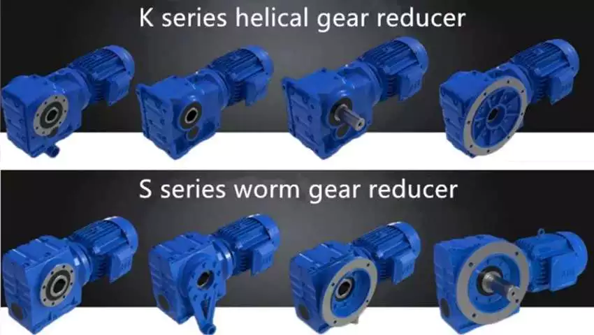
China Standard Wholesale Made In China Customization Industrial Worm Gear Speed Reducer Motor with high quality

Warranty: one
Applicable Industries: Garment Outlets, Creating Substance Shops, Production Plant, Equipment Fix Outlets, Food & Beverage Factory, Farms, Retail, Foodstuff Shop, Printing Retailers, Building works , Strength & Mining, Meals & Beverage Outlets, Other
Bodyweight (KG): 100 KG
Tailored assist: OEM, ODM, OBM, Support personalized
Gearing Arrangement: Other
Output Torque: 3,100 Nm -1,400,000 Nm
Input Velocity: 1
Output Speed: one
Solution title: Helical equipment reducer
Variety: Helical, helical equipment
Crankshaft Placement: Orthogonal
Other Attributes: Industrial
Torque: Min: 3,100 Nm (2,286.4427 ft.lb)
Highest: 1,four hundred,000 Nm (1,032,587.009 ft.lb)
Coloration: Blue
Packing: Wooden packing
Key word: gearbox units
Packaging Particulars: Wood packing
Port: ZheJiang

Agitator gear motor Mine reducer Bucket excavator reducer Helical gear reducer Conveyor belt reducer Helical equipment reducer Twin screw extruder reducer Extruder reducer Cylindrical spur equipment reducer Planetary reducer Belt conveyor reducer Reducer for inflator Specification

Type helical, helical gear
KeywordCoaxial helical gear reducer
Crankshaft PlacementOrthogonal
Other Characteristics Industrial
Minimum Torque 3,a hundred Nm (2,286.4427 ft.lb)
Maximum torque 1,400,000 Nm (1,032,587.009 ft.lb)
1. who are we?We are based mostly in ZheJiang , China, commence from 2013,sell to Southeast Asia(10.00%). There are overall about thirty folks in our place of work.2. how can we ensure top quality?Often a pre-generation sample just before mass productionAlways final Inspection ahead of cargo.3.what can you get from us?Equipment units.4. why ought to you get from us not from other suppliers?We have a comprehensive service technique, we can offer you with drawings before sales, and provide you with set up instructionsafter product sales, so you can buy with confidence.5. what providers can we offer?Accepted Shipping and delivery Phrases: FOB,CFR,CIF,EXW;Accepted Payment Forex:USD,EURAccepted Payment Type: T/T,L/C,Credit Card,PayPal,Western Union,Money,Escrow

Worm gear reducer

Cheaper than planetary gearboxes In many cases, worm gear reducers are a popular alternative to planetary gearboxes. A worm gear reducer is a mechanical device with vertical input and output shafts. This allows for very high reduction ratios. They are typically used in high-reduction situations such as machine tools.
Worm gears are cheaper than traditional gearboxes. They also have many benefits, including noise reduction. The output shaft of the worm gear reducer is almost 90 degrees from the motor input shaft, making it ideal for high-torque applications.
The worm gear reducer adopts an aluminum body, which is light in weight and high in operation efficiency. Additionally, they are available with hollow shafts and mounting flanges. In terms of initial cost, worm gear reducers are cheaper than planetary gearboxes. In addition, they have better efficiency and longer service life.
Worm drives are also ideal for portable battery-powered lifting equipment. The high gear ratio of the worm gear ensures that it does not reverse drive. The worm gear has a spring-applied brake that holds the motor in place.
Planetary gearboxes are popular among industrial users. The efficiency of planetary gearboxes is important for practical applications.
worm_reducer

pocket

The compact worm gear unit consists of a housing with an inner cavity. It has two side walls, one on either side of the front cover (13) and one on both sides of the rear cover (14). The front end cap is screwed onto the housing and the inner cavity is accessed through the rear end cap.
The compact worm gear unit can be configured to suit your application. They have many advantages, including saving space and increasing torque. The range includes single-envelope and double-envelope versions, available in a number of different power ratings. Additionally, they are IP65-rated, making them ideal for applications involving high radial or axial forces.
The compact worm reducer is a simple but effective worm drive. Its worm gear 16 meshes with the output shaft and rotates relatively stably. It also has a front-end cap and rear bearing. This enables the compact worm reducer to reduce vibration without damaging the output shaft.
Compact worm gear reducers are ideal for many applications and offer high efficiency. The compact design means you can mount them on the motor’s flange or base. Its durable construction makes it ideal for a variety of industries. They are extremely durable and can handle high-pressure and washdown conditions. They also come standard with a synthetic shaft.

high efficiency

High-efficiency worm gear reducers are ideal for applications that require precision, repeatability, and efficient performance. These reducers are designed with state-of-the-art servo motor technology to provide tight integration and an angular backlash of less than two arc minutes. The reduction ratio can be lower if the application requires it.
Rising energy costs have led to an increased focus on the efficiency of drives. In response to this, manufacturers have increased the efficiency of worm gear reducers through a number of technical improvements. By minimizing losses from rolling and sliding friction, worm gear reducers are more efficient than their counterparts.
The high-efficiency worm reducer is simple in design and has the characteristics of a compact structure, high-speed ratio, low power consumption, and self-locking. Other advantages of these reducers include low noise and long service life. Many also have built-in control systems that allow manual and remote adjustments. They also feature automatic shutdown protection and thermal protection.
High-efficiency worm reducers can be used for mechanical acceleration. The input hypoid gear is usually made of steel, while the output hypoid gear is usually made of bronze. Bronze is a soft metal that is good at absorbing shock loads. However, bronze requires work hardening to achieve optimum hardness. For large worm gears, this process can take 300 to 550 hours.
worm_reducer

low clearance

A low-clearance worm reducer is a device used to adjust the speed of a rotating shaft. It uses a worm gear consisting of two members. One worm is at one end of the shaft and the other is at the other end. Both worms are screwed into the synchronous drive structure.
Low clearance worm gear reducers can be produced on conventional worm gear production lines without overlapping investments. These units are usually made of soft rubber. Also, they are relatively quiet in operation. These machines are designed so that they are suitable for use in elevators. The softer material in the worm gear also helps absorb shock loads.
The tooth profile of the worm gear is designed to change with the axial movement of the worm. Worms have thinner right teeth and thicker left teeth. As the worm moves to the right, its teeth mesh with the worm gear, reducing backlash.
There are many different types of worm gears. The design of gears depends on many factors, including backlash, thermal design, friction factors and lubrication. Worm gears are made of several different materials. Some different types of materials used in worm gears require special lubrication.

quieter

The quieter worm reducer is designed to reduce the noise level of the rotating gear motor. The device has more gear teeth in meshing contact with the gears, which helps it run more quietly. In addition to being quieter than other transmissions, it’s also less expensive than its counterparts.
Worm gearboxes can be used for different applications, but they are not as efficient as helical gearboxes. Worm reducers are cheaper but less than 90% efficient. Higher gear ratios reduce efficiency, so worm gear reducers are better suited for applications that require low-speed torque. The cost of buying a worm gearbox will depend on the horsepower and gear ratios required.
Worm reducers are also more comfortable to use than planetary gearboxes. They don’t vibrate and heat up quickly, making them an excellent choice for low to medium horsepower applications. Worm gear reducers can be upgraded to improve their performance by combining with other gear trains or gearboxes.
worm_reducer

easy to replace

An easily replaceable worm gear reducer can save you a lot of money. A worm gear reducer is part of a chain drive and allows you to change gear ratios quickly and easily. Worm gear reducers can be easily replaced in a number of ways. It’s a good idea to read the manufacturer’s manual before replacing a worm gear reducer. Make sure you have the instructions available so you can refer to them in the future.
Worm gear reducers offer many advantages, including long service life and low noise. They are also designed with a 90-degree output shaft for easy installation. Another advantage of these gear reducers is that they can be used with both solid and hollow output shafts. This means less maintenance and downtime.
Worm gear reducers are widely used. Most gear manufacturers have large inventories. Worm gears also have uniform mounting dimensions. Dimensional consistency means you don’t have to worry about matching the shaft length and diameter to the worm gear. You can easily find a replacement worm gear reducer for your equipment.
When replacing the worm gear reducer, check the lubricating oil recommended by the machine. If not included, use original gear oil. Be sure to follow the manufacturer’s instructions carefully.

China Standard Wholesale Made In China Customization Industrial Worm Gear Speed Reducer Motor     with high quality China Standard Wholesale Made In China Customization Industrial Worm Gear Speed Reducer Motor     with high quality
editor by czh

China Standard NMRV +NRV small Worm Gear Reducer Worm Gearboxes brushless dc motor worm gearbox

Warranty: 1 year
Applicable Industries: Hotels, Garment Shops, Building Content Shops, Production Plant, Machinery Mend Retailers, Foods & Beverage Manufacturing facility, Farms, Cafe, Home Use, Retail, Foods Store, Printing Stores, Design works , Power & Mining, Meals & Beverage Shops, Other, Advertising Business, Manufacturing facility
Excess weight (KG): one hundred
Customized support: OEM, ODM, OBM
Gearing Arrangement: Worm
Output Torque: 2.7~1,760N.m
Input Velocity: 1400(4pole)
Output Velocity: 14-280rpm
Ratio: 5,7.5,ten,15,twenty,twenty five,30,40,50,60,80,100
Worm: 20CrMn Ti with carburizing and quenching, floor harness is fifty six-62HRC
Worm Gear: Copper-ten-3#
Packaging Information: regular export packing
Port: ZheJiang or HangZhou

NMRV +NRV little Worm Equipment Reducer Worm Gearboxes

RV sequence worm pace reducer,One ,double and universal velocity reducer.

one Higher top quality, It adopts difficult tooth equipment with higher accuracy2 Massive output torque,steady transmission with lower noise3 Higher heat-radiating effectiveness,classy form,sturdy provider daily life 4,Appropriate for omni-bearing installation4 Minimal sounds and sleek running5 Worm drive utilizes hollow flank worm6 Higher loading capability, minimal in temperature rise and the long valuable life7 Couple of distinction in between transmission ratio fee, I = 6~138008 Compact framework, modest dimensions, hassle-free maintenance9 Are dependent the special modulation blend system, so its convenient for them to fit all sorts of motors or to link with other electrical power input. The exact same sort of reducer can fit motors with various energy, so that its feasible for distinct varieties of equipment to blend or connect.
The gearboxes can be applied to numerous industrial location, these kinds of as Metallurgical, mines, lifting, transportation, petrochemical, building, textile, pharmaceutical, foodstuff, environmental, light-weight electric powered, plastic machine, paper, parking equipment and so on. Our specialized engineers can select design for you in accordance to your Request, and we also can supply our manufacturing facility catalogue for your reference.
Worm Equipment Speed Reducer/ gearbox
Specificatiion

Types
Rated Energy
Rated Ratio
Input Hole Dia.
Input Shaft Dia.
Output Gap Dia.
Output Shaft Dia.
RV571
.06KW~.12KW
five~60
Φ9
Φ9
Φ11
Φ11
RV030
.06KW~.25KW
5~eighty
Φ9(Φ11)
Φ9
Φ14
Φ14
RV040
.09KW~.55KW
five~100
Φ9(Φ11,Φ14)
Φ11
Φ18(Φ19)
Φ18
RV050
.12KW~1.5KW
5~a hundred
Φ11(Φ14,Φ19)
Φ14
Φ25(Φ24)
Φ25
RV063
.18KW~2.2KW
seven.5~a hundred
Φ14(Φ19,Φ24)
Φ19
Φ25(Φ28)
Φ25
RV075
.25KW~4.0KW
seven.5~one hundred
Φ14(Φ19,Φ24,Φ28)
Φ24
Φ28(Φ35)
Φ28
RV090
.37KW~4.0KW
seven.5~100
Φ19(Φ24,Φ28)
Φ24
Φ35(Φ38)
Φ35
RV110
.55KW~7.5KW
7.5~100
Φ19(Φ24,Φ28,Φ38)
Φ28
Φ42
Φ42
RV130
.75KW~7.5KW
seven.5~100
Φ24(Φ28,Φ38)
Φ30
Φ45
Φ45
RV150
two.2KW~15KW
7.5~100
Φ28(Φ38,Φ42)
Φ35
Φ50
Φ50

Firm Information

Packaging & Transport

FAQ
one. How to choose a gearbox which fulfills our need?
You can refer to our catalogue to choose the gearbox or we can help to select when you supply
the complex information of needed output torque, output speed and motor parameter and many others.

2. What information shall we give prior to positioning a purchase purchase?
a) Variety of the gearbox, ratio, input and output variety, enter flange, mounting placement, and motor informationetc.
b) Housing shade.
c) Buy quantity.
d) Other specific needs.

3. Can we acquire 1 computer of every single item for good quality tests?
Of course, we are glad to accept trial order for top quality testing

4. How extended is your shipping and delivery time?
Generally it is 5-ten days if the merchandise are in stock. or it is fifteen-twenty days if the items are not in stock.
Get in touch with Us

Choosing a Gearbox For Your Application

The gearbox is an essential part of bicycles. It is used for several purposes, including speed and force. A gearbox is used to achieve one or both of these goals, but there is always a trade-off. Increasing speed increases wheel speed and forces on the wheels. Similarly, increasing pedal force increases the force on the wheels. This makes it easier for cyclists to accelerate their bicycles. However, this compromise makes the gearbox less efficient than an ideal one.
gearbox

Dimensions

Gearboxes come in different sizes, so the size of your unit depends on the number of stages. Using a chart to determine how many stages are required will help you determine the dimensions of your unit. The ratios of individual stages are normally greater at the top and get smaller as you get closer to the last reduction. This information is important when choosing the right gearbox for your application. However, the dimensions of your gearbox do not have to be exact. Some manufacturers have guides that outline the required dimensions.
The service factor of a gearbox is a combination of the required reliability, the actual service condition, and the load that the gearbox will endure. It can range from 1.0 to 1.4. If the service factor of a gearbox is 1.0, it means that the unit has just enough capacity to meet your needs, but any extra requirements could cause the unit to fail or overheat. However, service factors of 1.4 are generally sufficient for most industrial applications, since they indicate that a gearbox can withstand 1.4 times its application requirement.
Different sizes also have different shapes. Some types are concentric, while others are parallel or at a right angle. The fourth type of gearbox is called shaft mount and is used when mounting the gearbox by foot is impossible. We will discuss the different mounting positions later. In the meantime, keep these dimensions in mind when choosing a gearbox for your application. If you have space constraints, a concentric gearbox is usually your best option.

Construction

The design and construction of a gearbox entails the integration of various components into a single structure. The components of a gearbox must have sufficient rigidity and adequate vibration damping properties. The design guidelines note the approximate values for the components and recommend the production method. Empirical formulas were used to determine the dimensions of the various components. It was found that these methods can simplify the design process. These methods are also used to calculate the angular and axial displacements of the components of the gearbox.
In this project, we used a 3D modeling software called SOLIDWORKS to create a 3-D model of a gear reducer. We used this software to simulate the structure of the gearbox, and it has powerful design automation tools. Although the gear reducer and housing are separate parts, we model them as a single body. To save time, we also removed the auxiliary elements, such as oil inlets and oil level indicators, from the 3D model.
Our method is based on parameter-optimized deep neural networks (DBNs). This model has both supervised and unsupervised learning capabilities, allowing it to be self-adaptive. This method is superior to traditional methods, which have poor self-adaptive feature extraction and shallow network generalization. Our algorithm is able to recognize faults in different states of the gearbox using its vibration signal. We have tested our model on two gearboxes.
With the help of advanced material science technologies, we can now manufacture the housing for the gearbox using high-quality steel and aluminium alloys. In addition, advanced telematics systems have increased the response time of manufacturers. These technologies are expected to create tremendous opportunities in the coming years and fuel the growth of the gearbox housing market. There are many different ways to construct a gearbox, and these techniques are highly customizable. In this study, we will consider the design and construction of various gearbox types, as well as their components.
gearbox

Working

A gearbox is a mechanical device that transmits power from one gear to another. The different types of gears are called planetary gears and are used in a variety of applications. Depending on the type of gearbox, it may be concentric, parallel, or at a right angle. The fourth type of gearbox is a shaft mount. The shaft mount type is used in applications that cannot be mounted by foot. The various mounting positions will be discussed later.
Many design guidelines recommend a service factor of 1.0, which needs to be adjusted based on actual service conditions. This factor is the combined measure of external load, required reliability, and overall gearbox life. In general, published service factors are the minimum requirements for a particular application, but a higher value is necessary for severe loading. This calculation is also recommended for high-speed gearboxes. However, the service factor should not be a sole determining factor in the selection process.
The second gear of a pair of gears has more teeth than the first gear. It also turns slower, but with greater torque. The second gear always turns in the opposite direction. The animation demonstrates this change in direction. A gearbox can also have more than one pair of gears, and a first gear may be used for the reverse. When a gear is shifted from one position to another, the second gear is engaged and the first gear is engaged again.
Another term used to describe a gearbox is “gear box.” This term is an interchangeable term for different mechanical units containing gears. Gearboxes are commonly used to alter speed and torque in various applications. Hence, understanding the gearbox and its parts is essential to maintaining your car’s performance. If you want to extend the life of your vehicle, be sure to check the gearbox’s efficiency. The better its functioning, the less likely it is to fail.

Advantages

Automatic transmission boxes are almost identical to mechanical transmission boxes, but they also have an electronic component that determines the comfort of the driver. Automatic transmission boxes use special blocks to manage shifts effectively and take into account information from other systems, as well as the driver’s input. This ensures accuracy and positioning. The following are a few gearbox advantages:
A gearbox creates a small amount of drag when pedaling, but this drag is offset by the increased effort to climb. The external derailleur system is more efficient when adjusted for friction, but it does not create as little drag in dry conditions. The internal gearbox allows engineers to tune the shifting system to minimize braking issues, pedal kickback, and chain growth. As a result, an internal gearbox is a great choice for bikes with high-performance components.
Helical gearboxes offer some advantages, including a low noise level and lower vibration. They are also highly durable and reliable. They can be extended in modular fashion, which makes them more expensive. Gearboxes are best for applications involving heavy loads. Alternatively, you can opt for a gearbox with multiple teeth. A helical gearbox is more durable and robust, but it is also more expensive. However, the benefits far outweigh the disadvantages.
A gearbox with a manual transmission is often more energy-efficient than one with an automatic transmission. Moreover, these cars typically have lower fuel consumption and higher emissions than their automatic counterparts. In addition, the driver does not have to worry about the brakes wearing out quickly. Another advantage of a manual transmission is its affordability. A manual transmission is often available at a lower cost than its automatic counterpart, and repairs and interventions are easier and less costly. And if you have a mechanical problem with the gearbox, you can control the fuel consumption of your vehicle with appropriate driving habits.
gearbox

Application

While choosing a gearbox for a specific application, the customer should consider the load on the output shaft. High impact loads will wear out gear teeth and shaft bearings, requiring higher service factors. Other factors to consider are the size and style of the output shaft and the environment. Detailed information on these factors will help the customer choose the best gearbox. Several sizing programs are available to determine the most appropriate gearbox for a specific application.
The sizing of a gearbox depends on its input speed, torque, and the motor shaft diameter. The input speed must not exceed the required gearbox’s rating, as high speeds can cause premature seal wear. A low-backlash gearbox may be sufficient for a particular application. Using an output mechanism of the correct size may help increase the input speed. However, this is not recommended for all applications. To choose the right gearbox, check the manufacturer’s warranty and contact customer service representatives.
Different gearboxes have different strengths and weaknesses. A standard gearbox should be durable and flexible, but it must also be able to transfer torque efficiently. There are various types of gears, including open gearing, helical gears, and spur gears. Some of the types of gears can be used to power large industrial machines. For example, the most popular type of gearbox is the planetary drive gearbox. These are used in material handling equipment, conveyor systems, power plants, plastics, and mining. Gearboxes can be used for high-speed applications, such as conveyors, crushers, and moving monorail systems.
Service factors determine the life of a gearbox. Often, manufacturers recommend a service factor of 1.0. However, the actual value may be higher or lower than that. It is often useful to consider the service factor when choosing a gearbox for a particular application. A service factor of 1.4 means that the gearbox can handle 1.4 times the load required. For example, a 1,000-inch-pound gearbox would need a 1,400-inch-pound gearbox. Service factors can be adjusted to suit different applications and conditions.

China Standard NMRV +NRV small Worm Gear Reducer Worm Gearboxes     brushless dc motor worm gearboxChina Standard NMRV +NRV small Worm Gear Reducer Worm Gearboxes     brushless dc motor worm gearbox
editor by czh

China wholesaler Wholesale price worm gearbox WPO 50 speed reducer motor reductor worm gear backdrive

Warranty: 1 12 months, 1 Year
Applicable Industries: Accommodations, Garment Shops, Building Substance Outlets, Manufacturing Plant, Equipment Fix Outlets, Restaurant, Power & Mining, Other, Reducer
Fat (KG): one hundred KG
Customized assistance: OEM, ODM, OBM, OEM, ODM, OBM
Gearing Arrangement: Worm
Output Torque: ninety ~ 3000 Nm
Input Speed: 1450 RPM
Output Velocity: .2 ~ one hundred twenty RPM
Variety: Reducer
Packaging Specifics: Wood scenario
Port: ZheJiang

Product Information [email protected] Display DESCRIPTION Manufacturing facility Screening Tools Roughness Tester Metallography Microscope Micro vickers Contourograph Coordinate Measuring Machine Peak Guage Firm Details ZheJiang CZPT Driving Tools Technology Co., Ltd. ZheJiang CZPT Driving Tools Technology Co., Ltd. is a expert R&D and maker of couplings, cardan shafts and gearboxes with a registered cash of 36.88 million. The business addresses an spot of 55 acres, with a production workshop of 12,000 square meters and 108 manufacturing gear. With strong energy, innovative technological process and more than 20 several years of producing expertise, the firm has passed ISO9001 quality management program certification. It was recognized as a high-tech enterprise by ZheJiang Province Industry and Data Engineering. It is a member device of transmission connecting components of China Equipment Common Components Industry Association, and has 8 utility model patent certificates. The company’s foremost merchandise largely include elastic couplings, rigid couplings and other dozens of sequence of couplings with 1000’s of requirements, which are commonly employed in metallurgy, mining, cement, paper, electrical electricity, chemical industry, wind power, petroleum, port machinery, and many others. industry. It has provided strong technological and products support for the import and localization of couplings of a lot of domestic metal mills, and has won unanimous praise from the greater part of consumers. Get in touch with us[email protected] COOPERATIVE Customers OUR Certification FAQ 1: Are you a investing organization or a company ?We are a specialist producer of couplings and common joints.2:Why select CZPT Driving Equipment Engineering?As a expert manufacturer of coupling and common joints, we have a skillful team of workers and designers To provide our buyers with initial-class services.3: Can You Strictly Follow The Tolerance on The Drawing And Meet up with The Higher Precision?Of course, we can, we can supply large precision components and make the areas as your drawing.5:How to deal with the components obtained when they are discovered to be in poor high quality?A: In circumstance of non- conformance, you should get in touch with us immediately, we will check out the difficulties and have them reworked or repaired at the first time. If none of these operates, we support a refund.six: Can I get a Reducer motor sample?A : Of Course . We source cost-free samples for you check out top quality.

Advantages and disadvantages of worm gear reducer

If you are looking for a worm gear reducer, you have come to the right place. This article will cover the pros and cons of worm gear reducers and discuss the different types available. You will learn about multi-head worm gear reducers, hollow shaft worm gear reducers as well as hypoid gear sets and motors.
worm_reducer

Hollow shaft worm gear reducer

Hollow shaft worm gear reducers are used to connect two or more rotating parts. They are available in single-axis and dual-axis versions and can be connected to various motor types. They can also have different ratios. The ratios of these gear reducers depend on the quality of the bearings and assembly process.
Hollow shaft worm gear reducers are made of bronze worm gears and cast iron hubs. The gears are lubricated with synthetic oil. They are lightweight and durable. They can be installed in various engine housings. Additionally, these gear reducers are available in a variety of sizes. The range includes 31.5, 40, 50, 63, and 75mm models. Other sizes are available upon request.
In addition to worm gear reducers, there are also helical gear reducers. These reducers can achieve very low output speeds. They are also suitable for all-around installations. In addition, the advantage of a multi-stage reducer is that it is more efficient than a single-stage gear reducer. They also feature low noise, low vibration, and low energy consumption.
Hollow shaft worm gear reducers are generally less expensive and last longer. They are also a suitable replacement for solid shaft gearboxes for machines that require high torque without compromising strength. Typical gear arrangements include worm, spur, helical and bevel gears. Gear ratio is the ratio of input torque to output torque.

Multi-head worm gear reducer

The multi-head worm gear reducer is used to reduce the speed of the machine. It uses friction to hold the worm in place while transmitting power. These gears can also be called ground worms and hardened worm gears. They are useful in conveying systems and most engineering applications.
Multiple worm reducers have a large number of gear ratios. These gear designs have a central cross-section that forms the front and rear boundaries of the worm gear. This design is a better choice than other worm gears because it is less prone to wear and can be used with a variety of motors and other electronics.
Adjustable multi-head worm gear reducer to reduce axial play. Usually, the backlash on the left and right sides of the worm is the same. However, if you need less backlash, you can buy a double lead worm gear. This design is ideal for precision applications requiring small clearances. The lead of the opposing teeth of the double worm gear is different from the right side, so the backlash can be adjusted without adjusting the center distance between the worm gears.
Worm gear reducers are available from a variety of manufacturers. Many gear manufacturers stock these gears. Since the gear ratios are standardized, there is no need to adjust the height, diameter, or length of the shaft. Worm gears have fewer moving parts, which means they require less maintenance.
worm_reducer

Hypoid Gear Set

Worm gears are the most common type of gear. While these gears are great for high-to-low ratios, hypoid gear sets are much more efficient in all ratios. This difference is due to higher torque density, better geometry and materials, and the way hypoid gears transmit force differently than worm gears.
Hypoid gear sets have curved helical teeth. This results in smooth gear meshing and little noise. This is because the hypoid gears start to slowly contact each other, but the contact progresses smoothly from tooth to tooth. This reduces friction and wears, thereby increasing the efficiency of the machine.
The main advantages of hypoid gears over worm gears are higher torque capacity and lower noise levels. Although their upfront cost may be higher, hypoid gears are more efficient than worm gears. They are able to handle higher initial inertia loads and can deliver more torque with a smaller motor. This saves money in the long run.
Another advantage of hypoid gears is the lower operating temperature. They also do not require oil lubrication or ventilation holes, reducing maintenance requirements. The hypoid gear set is maintenance-free, and the grease on the hypoid gear set lasts for decades.

Hypoid gear motor

A hypoid gear motor is a good choice for a worm gear reducer as it allows for a smaller motor and more efficient energy transfer. In fact, a 1 hp motor driving a hypoid reducer can provide the same output as a 1/2 hp motor driving a worm reducer. A study by Nissei compared two gear reduction methods and determined that a hypoid gear motor produces more torque and power than a worm reducer when using a fixed reduction ratio of 60:1. The study also showed that the 1/2 HP hypoid gear motor is more energy efficient and reduces electricity bills.
Worm reducers run hotter than hypoid gears, and the added heat can shorten their lifespan. This can cause components to wear out faster, and the motor may require more frequent oil changes. In addition, hypoid gear motors are more expensive to manufacture.
Compared to worm gears, hypoid gears offer higher efficiency and lower operating noise. However, they require additional processing techniques. They are made of bronze, a softer metal capable of absorbing heavy shock loads. Worm drives require work hardening and are less durable. Operating noise is reduced by up to 30%, and hypoid gears are less prone to breakage than bevel gears.
Hypoid gear motors are prized for their efficiency and are used in applications requiring lower torque. A unique hypoid tooth profile reduces friction. In addition, hypoid gear motors are ideal for applications where space is limited. These geared motors are often used with pulleys and levers.

R series worm gear reducer

R series worm gear reducers have a variety of characteristics that make them ideal for different applications. Its high rigidity cast iron housing and rigid side gears are designed for smooth drive and low noise. It also features high load capacity and long service life. Additionally, it can be assembled into many different configurations as required.
High efficiency, large output torque and good use efficiency. It comes in four basic models ranging from 0.12KW to 200KW. It can be matched with right angle bevel gearbox to provide large speed ratio and high torque. This combination is also suitable for low output and high torque.
worm_reducer

AGKNX Electric Worm Gear Reducer

AGKNX Electric worm gear reducers are available with NEMA C-face mounting flanges for a variety of motors. These reducers feature double lip oil seals, an aluminum alloy housing, and two bearings on the input and output shafts. These reducers are rust-proof and have epoxy paint on the inside. They are available in a variety of ratios, from 7.5:1 to 100:1.
Worm reducers are one of the most cost-effective and compact gears. These reducers increase output torque while reducing input speed. AGKNX Electric’s worm gear reducers are pre-installed with Mobil SHC634 Synthetic Gear Oil. These reducers have an internal oil gallery guide to protect the shaft. They also have a one-piece cast iron housing.
AGKNX Electric Corporation is the leading independent distributor of electric motors in the United States. They have eight strategically located warehouses, enabling them to ship most orders on the same day. They offer motors of various sizes up to 20,000 hp. They also offer a variety of motor controls and variable speed drives.
China wholesaler Wholesale price worm gearbox WPO 50 speed reducer motor reductor     worm gear backdriveChina wholesaler Wholesale price worm gearbox WPO 50 speed reducer motor reductor     worm gear backdrive

China supplier Transmission Motor Gearbox Unit Wp Nmrv Swl Screw Drive Lifts Stepper Cyclo Cycloidal Extruder Helical Planetary Bevel Worm Speed Variator Gear Reducer Gearbox near me manufacturer

Product Description

Transmission Motor Gearbox Unit Wp Nmrv Swl Screw Drive Lifts Stepper Cyclo Cycloidal Extruder Helical Planetary Bevel Worm Speed Variator Gear Reducer Gearbox

Features

1. Compact structure and simple assembly;
2. Wide speed ranges and high torque;
3. Low noise, good sealing performance, high efficiency;
4. Stable and safe, long lifetime, universal;
5. Multi-structure, various assembling methods


Product Photos


Product Description


                                                                                      ANG Helical Gear Reducer
Model R17 ~ 187, F37-177, K37-187, S37-97, HB01-26
Input power 0.06kw ~ 5000kw
Input speed 750rpm ~ 3000rpm
Reduction ratio 1/1.3 ~ 1/27000
Input motor AC (1 phase or 3 phase) / DC / BLDC motor
Install type Foot / Solid shaft / Hollow shaft / Output flange…
Efficiency 94% ~ 98 % for R F K series
Material of housing die-cast aluminum / Cast iron / Stainless steel
Precision of gear Accurate grinding, class 6
Heat treatment Carburizing and quenching
Accessories Brake / Flange / Motor adapter / Torque arm …

Advantages


FAQ


Q: Can you make the gearbox with customization?
A: Yes, we can customize per your request, like power, voltage, speed, shaft size, flange, terminal box, IP grade, etc.

Q: Do you provide samples?
A: Yes. The sample is available for testing.

Q: What is your MOQ?
A: It is 1pcs for the beginning of our business.

Q: What’s your lead time?
A: Standard product need 5-30days, a bit longer for customized products.

Q: Do you provide technical support?
A: Yes. Our company have design and development team, we can provide technical support if you
need.

Q: How to ship to us?
A: It is available by air, or by sea, or by train.

Q: How to pay the money?
A: T/T and L/C are preferred, with a different currency, including USD, EUR, RMB, etc.

Q: How can I know the product is suitable for me?
A: >1ST confirm drawing and specification >2nd test sample >3rd start mass production.

Q: Can I come to your company to visit?
A: Yes, you are welcome to visit us at any time.

Q: How shall we contact you?
A: You can send inquiry directly, and we will respond within 24 hours.
 

Screw Shaft Features Explained

When choosing the screw shaft for your application, you should consider the features of the screws: threads, lead, pitch, helix angle, and more. You may be wondering what these features mean and how they affect the screw’s performance. This article explains the differences between these factors. The following are the features that affect the performance of screws and their properties. You can use these to make an informed decision and purchase the right screw. You can learn more about these features by reading the following articles.

Threads

The major diameter of a screw thread is the larger of the 2 extreme diameters. The major diameter of a screw is also known as the outside diameter. This dimension can’t be directly measured, but can be determined by measuring the distance between adjacent sides of the thread. In addition, the mean area of a screw thread is known as the pitch. The diameter of the thread and pitch line are directly proportional to the overall size of the screw.
The threads are classified by the diameter and pitch. The major diameter of a screw shaft has the largest number of threads; the smaller diameter is called the minor diameter. The thread angle, also known as the helix angle, is measured perpendicular to the axis of the screw. The major diameter is the largest part of the screw; the minor diameter is the lower end of the screw. The thread angle is the half distance between the major and minor diameters. The minor diameter is the outer surface of the screw, while the top surface corresponds to the major diameter.
The pitch is measured at the crest of a thread. In other words, a 16-pitch thread has a diameter of 1 sixteenth of the screw shaft’s diameter. The actual diameter is 0.03125 inches. Moreover, a large number of manufacturers use this measurement to determine the thread pitch. The pitch diameter is a critical factor in successful mating of male and female threads. So, when determining the pitch diameter, you need to check the thread pitch plate of a screw.
screwshaft

Lead

In screw shaft applications, a solid, corrosion-resistant material is an important requirement. Lead screws are a robust choice, which ensure shaft direction accuracy. This material is widely used in lathes and measuring instruments. They have black oxide coatings and are suited for environments where rusting is not acceptable. These screws are also relatively inexpensive. Here are some advantages of lead screws. They are highly durable, cost-effective, and offer high reliability.
A lead screw system may have multiple starts, or threads that run parallel to each other. The lead is the distance the nut travels along the shaft during a single revolution. The smaller the lead, the tighter the thread. The lead can also be expressed as the pitch, which is the distance between adjacent thread crests or troughs. A lead screw has a smaller pitch than a nut, and the smaller the lead, the greater its linear speed.
When choosing lead screws, the critical speed is the maximum number of revolutions per minute. This is determined by the minor diameter of the shaft and its length. The critical speed should never be exceeded or the lead will become distorted or cracked. The recommended operational speed is around 80 percent of the evaluated critical speed. Moreover, the lead screw must be properly aligned to avoid excessive vibrations. In addition, the screw pitch must be within the design tolerance of the shaft.

Pitch

The pitch of a screw shaft can be viewed as the distance between the crest of a thread and the surface where the threads meet. In mathematics, the pitch is equivalent to the length of 1 wavelength. The pitch of a screw shaft also relates to the diameter of the threads. In the following, the pitch of a screw is explained. It is important to note that the pitch of a screw is not a metric measurement. In the following, we will define the 2 terms and discuss how they relate to 1 another.
A screw’s pitch is not the same in all countries. The United Kingdom, Canada, and the United States have standardized screw threads according to the UN system. Therefore, there is a need to specify the pitch of a screw shaft when a screw is being manufactured. The standardization of pitch and diameter has also reduced the cost of screw manufacturing. Nevertheless, screw threads are still expensive. The United Kingdom, Canada, and the United States have introduced a system for the calculation of screw pitch.
The pitch of a lead screw is the same as that of a lead screw. The diameter is 0.25 inches and the circumference is 0.79 inches. When calculating the mechanical advantage of a screw, divide the diameter by its pitch. The larger the pitch, the more threads the screw has, increasing its critical speed and stiffness. The pitch of a screw shaft is also proportional to the number of starts in the shaft.

Helix angle

The helix angle of a screw shaft is the angle formed between the circumference of the cylinder and its helix. Both of these angles must be equal to 90 degrees. The larger the lead angle, the smaller the helix angle. Some reference materials refer to angle B as the helix angle. However, the actual angle is derived from calculating the screw geometry. Read on for more information. Listed below are some of the differences between helix angles and lead angles.
High helix screws have a long lead. This length reduces the number of effective turns of the screw. Because of this, fine pitch screws are usually used for small movements. A typical example is a 16-mm x 5-inch screw. Another example of a fine pitch screw is a 12x2mm screw. It is used for small moves. This type of screw has a lower lead angle than a high-helix screw.
A screw’s helix angle refers to the relative angle of the flight of the helix to the plane of the screw axis. While screw helix angles are not often altered from the standard square pitch, they can have an effect on processing. Changing the helix angle is more common in two-stage screws, special mixing screws, and metering screws. When a screw is designed for this function, it should be able to handle the materials it is made of.
screwshaft

Size

The diameter of a screw is its diameter, measured from the head to the shaft. Screw diameters are standardized by the American Society of Mechanical Engineers. The diameters of screws range from 3/50 inches to 16 inches, and more recently, fractions of an inch have been added. However, shaft diameters may vary depending on the job, so it is important to know the right size for the job. The size chart below shows the common sizes for screws.
Screws are generally referred to by their gauge, which is the major diameter. Screws with a major diameter less than a quarter of an inch are usually labeled as #0 to #14 and larger screws are labeled as sizes in fractions of an inch. There are also decimal equivalents of each screw size. These measurements will help you choose the correct size for your project. The screws with the smaller diameters were not tested.
In the previous section, we described the different shaft sizes and their specifications. These screw sizes are usually indicated by fractions of an inch, followed by a number of threads per inch. For example, a ten-inch screw has a shaft size of 2” with a thread pitch of 1/4″, and it has a diameter of 2 inches. This screw is welded to a two-inch Sch. 40 pipe. Alternatively, it can be welded to a 9-inch O.A.L. pipe.
screwshaft

Shape

Screws come in a wide variety of sizes and shapes, from the size of a quarter to the diameter of a U.S. quarter. Screws’ main function is to hold objects together and to translate torque into linear force. The shape of a screw shaft, if it is round, is the primary characteristic used to define its use. The following chart shows how the screw shaft differs from a quarter:
The shape of a screw shaft is determined by 2 features: its major diameter, or distance from the outer edge of the thread on 1 side to the inner smooth surface of the shaft. These are generally 2 to 16 millimeters in diameter. Screw shafts can have either a fully threaded shank or a half-threaded shank, with the latter providing better stability. Regardless of whether the screw shaft is round or domed, it is important to understand the different characteristics of a screw before attempting to install it into a project.
The screw shaft’s diameter is also important to its application. The ball circle diameter refers to the distance between the center of 2 opposite balls in contact with the grooves. The root diameter, on the other hand, refers to the distance between the bottommost grooves of the screw shaft. These are the 2 main measurements that define the screw’s overall size. Pitch and nominal diameter are important measurements for a screw’s performance in a particular application.

Lubrication

In most cases, lubrication of a screw shaft is accomplished with grease. Grease is made up of mineral or synthetic oil, thickening agent, and additives. The thickening agent can be a variety of different substances, including lithium, bentonite, aluminum, and barium complexes. A common classification for lubricating grease is NLGI Grade. While this may not be necessary when specifying the type of grease to use for a particular application, it is a useful qualitative measure.
When selecting a lubricant for a screw shaft, the operating temperature and the speed of the shaft determine the type of oil to use. Too much oil can result in heat buildup, while too little can lead to excessive wear and friction. The proper lubrication of a screw shaft directly affects the temperature rise of a ball screw, and the life of the assembly. To ensure the proper lubrication, follow the guidelines below.
Ideally, a low lubrication level is appropriate for medium-sized feed stuff factories. High lubrication level is appropriate for larger feed stuff factories. However, in low-speed applications, the lubrication level should be sufficiently high to ensure that the screws run freely. This is the only way to reduce friction and ensure the longest life possible. Lubrication of screw shafts is an important consideration for any screw.

China supplier Transmission Motor Gearbox Unit Wp Nmrv Swl Screw Drive Lifts Stepper Cyclo Cycloidal Extruder Helical Planetary Bevel Worm Speed Variator Gear Reducer Gearbox   near me manufacturer China supplier Transmission Motor Gearbox Unit Wp Nmrv Swl Screw Drive Lifts Stepper Cyclo Cycloidal Extruder Helical Planetary Bevel Worm Speed Variator Gear Reducer Gearbox   near me manufacturer

China Best Sales Reducer Gear Japan Motor Worm Mill CNC Lathe with Live Tooling with Free Design Custom

Product Description

DAS DS-25WS/25WL Outer/Inner Whirlwind Milling CNC Lathe Machine
(Optional Automation)

Product Description

1.Machine tool base is resin sand cast integrally, boasts high vibration resistance, small machine deformation.


2. Yaskawa servo drive is used for main shaft to ensure the high precision requirement of multiple thread screw.


3.The main shaft contains high precision Japan NSK precise bearing with the inner cone of main shaft directly mounted with elastic chuck in order to ensure the rotation precision.


4.ZheJiang famous HIWIN / PMI high-precision Class P3 ball-bearing screw rod is used for the transmission portion of the machine tool.


5.The machine USES ZheJiang SYNTEC system, Japan YASKAWA servo motor control.


6.Machine adopts roller CZPT rail structure, can withstand the larger cutting and resistance to impact.


7.The machine can be used for processing single head or multi-head worm.


8. Cutter shaft can realize large angle rotation.


Model

DS-25W

Max.Processing length(mm)

250

Max.processing modulus(m)

1.5

Max.processing diameter(mm)

32

Tailstock function

Have(optional)

Knife CZPT bush

Have

Milling Type

Outer Whirlwind Milling

Spindle Max.speed(r/min)

1500

Spindle motor power(KW)

5.9

Tool shaft Max. speed

3000(factory setting)

Tool shaft motor power(KW)

3.1

Tool form

Forming Tool

Max.installed tool quantity

1

System Min.resolution

0.001

X/Z axis travel(mm)

100/250

X/Z axis fast moving speed(r/min)

12

X/Z axis repeatability(mm)

±0.005

Taper(mm)

≤0.005/100

Circle processing precision(mm)

≤0.003

X axis motor power(KW)

1.3

Z axis motor power(KW)

1.3

Hydraulic motor power(KW)

0.75

Water tank motor power(KW)

0.12

Coolant tank capacity(L)

100

Machine power(kw)

22

Net Weight(KG)

2800

Machine Dimensions(LxWxH)(mm)

1700*1600*1900

1. Machine tool control system uses ZheJiang SYNTEC 6TA-T3S system. Other Brand including GSK,Fanuc,Siemens are OK!

2. Machine body is cast in 1 piece. The lathe bed tilts by 45°and the inclined placement of lathe carriage.

3.ZheJiang ‘s high-precision spindle, comprising Japan CZPT precise bearings; three-jaw hydraulic chuck or other elastic clamp can be directly fitted on the main shaft flange.

4.The drive part of machine tool uses HIWIN/PMI high precision P3 class ball bearing screw and high speed linear slide rail.

Good Feedback

     HangZhou Xihu (West Lake) Dis. Guoqiang Daosheng Industrial Co., Ltd. is located in Chencun, the important machinery town in Xihu (West Lake) Dis. District,HangZhou. Sticking to the human-centering management, we are in possession of a group of highly competent technical personnel, a market oriented experienced sales team. In the gesture of sincere cooperation, we strive to establish a promise keeping and quality .

     Our major products include CNC series gang tool type lathes , turret lathes, take heart-type lathes and milling-type lathes, featuring space saving, low cost and diversified arrangement etc.

They can also meet the demand for precise processing of different products. The products find widespread application in the manufacture of cars, motorcycles and accessories thereof,electronic industry, optical instruments, clocks and watches as well as special motors etc.

     We have precise lathe equipment, complete quality guarantee system, prompt goods supply as well as perfect after-sales service,which ensure us the first consideration when you purchase high-precision machine tools.

What Are Screw Shaft Threads?

A screw shaft is a threaded part used to fasten other components. The threads on a screw shaft are often described by their Coefficient of Friction, which describes how much friction is present between the mating surfaces. This article discusses these characteristics as well as the Material and Helix angle. You’ll have a better understanding of your screw shaft’s threads after reading this article. Here are some examples. Once you understand these details, you’ll be able to select the best screw nut for your needs.
screwshaft

Coefficient of friction between the mating surfaces of a nut and a screw shaft

There are 2 types of friction coefficients. Dynamic friction and static friction. The latter refers to the amount of friction a nut has to resist an opposing motion. In addition to the material strength, a higher coefficient of friction can cause stick-slip. This can lead to intermittent running behavior and loud squeaking. Stick-slip may lead to a malfunctioning plain bearing. Rough shafts can be used to improve this condition.
The 2 types of friction coefficients are related to the applied force. When applying force, the applied force must equal the nut’s pitch diameter. When the screw shaft is tightened, the force may be removed. In the case of a loosening clamp, the applied force is smaller than the bolt’s pitch diameter. Therefore, the higher the property class of the bolt, the lower the coefficient of friction.
In most cases, the screwface coefficient of friction is lower than the nut face. This is because of zinc plating on the joint surface. Moreover, power screws are commonly used in the aerospace industry. Whether or not they are power screws, they are typically made of carbon steel, alloy steel, or stainless steel. They are often used in conjunction with bronze or plastic nuts, which are preferred in higher-duty applications. These screws often require no holding brakes and are extremely easy to use in many applications.
The coefficient of friction between the mating surfaces of t-screws is highly dependent on the material of the screw and the nut. For example, screws with internal lubricated plastic nuts use bearing-grade bronze nuts. These nuts are usually used on carbon steel screws, but can be used with stainless steel screws. In addition to this, they are easy to clean.

Helix angle

In most applications, the helix angle of a screw shaft is an important factor for torque calculation. There are 2 types of helix angle: right and left hand. The right hand screw is usually smaller than the left hand one. The left hand screw is larger than the right hand screw. However, there are some exceptions to the rule. A left hand screw may have a greater helix angle than a right hand screw.
A screw’s helix angle is the angle formed by the helix and the axial line. Although the helix angle is not usually changed, it can have a significant effect on the processing of the screw and the amount of material conveyed. These changes are more common in 2 stage and special mixing screws, and metering screws. These measurements are crucial for determining the helix angle. In most cases, the lead angle is the correct angle when the screw shaft has the right helix angle.
High helix screws have large leads, sometimes up to 6 times the screw diameter. These screws reduce the screw diameter, mass, and inertia, allowing for higher speed and precision. High helix screws are also low-rotation, so they minimize vibrations and audible noises. But the right helix angle is important in any application. You must carefully choose the right type of screw for the job at hand.
If you choose a screw gear that has a helix angle other than parallel, you should select a thrust bearing with a correspondingly large center distance. In the case of a screw gear, a 45-degree helix angle is most common. A helix angle greater than zero degrees is also acceptable. Mixing up helix angles is beneficial because it allows for a variety of center distances and unique applications.
screwshaft

Thread angle

The thread angle of a screw shaft is measured from the base of the head of the screw to the top of the screw’s thread. In America, the standard screw thread angle is 60 degrees. The standard thread angle was not widely adopted until the early twentieth century. A committee was established by the Franklin Institute in 1864 to study screw threads. The committee recommended the Sellers thread, which was modified into the United States Standard Thread. The standardized thread was adopted by the United States Navy in 1868 and was recommended for construction by the Master Car Builders’ Association in 1871.
Generally speaking, the major diameter of a screw’s threads is the outside diameter. The major diameter of a nut is not directly measured, but can be determined with go/no-go gauges. It is necessary to understand the major and minor diameters in relation to each other in order to determine a screw’s thread angle. Once this is known, the next step is to determine how much of a pitch is necessary to ensure a screw’s proper function.
Helix angle and thread angle are 2 different types of angles that affect screw efficiency. For a lead screw, the helix angle is the angle between the helix of the thread and the line perpendicular to the axis of rotation. A lead screw has a greater helix angle than a helical one, but has higher frictional losses. A high-quality lead screw requires a higher torque to rotate. Thread angle and lead angle are complementary angles, but each screw has its own specific advantages.
Screw pitch and TPI have little to do with tolerances, craftsmanship, quality, or cost, but rather the size of a screw’s thread relative to its diameter. Compared to a standard screw, the fine and coarse threads are easier to tighten. The coarser thread is deeper, which results in lower torques. If a screw fails because of torsional shear, it is likely to be a result of a small minor diameter.

Material

Screws have a variety of different sizes, shapes, and materials. They are typically machined on CNC machines and lathes. Each type is used for different purposes. The size and material of a screw shaft are influenced by how it will be used. The following sections give an overview of the main types of screw shafts. Each 1 is designed to perform a specific function. If you have questions about a specific type, contact your local machine shop.
Lead screws are cheaper than ball screws and are used in light-duty, intermittent applications. Lead screws, however, have poor efficiency and are not recommended for continuous power transmission. But, they are effective in vertical applications and are more compact. Lead screws are typically used as a kinematic pair with a ball screw. Some types of lead screws also have self-locking properties. Because they have a low coefficient of friction, they have a compact design and very few parts.
Screws are made of a variety of metals and alloys. Steel is an economical and durable material, but there are also alloy steel and stainless steel types. Bronze nuts are the most common and are often used in higher-duty applications. Plastic nuts provide low-friction, which helps reduce the drive torques. Stainless steel screws are also used in high-performance applications, and may be made of titanium. The materials used to create screw shafts vary, but they all have their specific functions.
Screws are used in a wide range of applications, from industrial and consumer products to transportation equipment. They are used in many different industries, and the materials they’re made of can determine their life. The life of a screw depends on the load that it bears, the design of its internal structure, lubrication, and machining processes. When choosing screw assemblies, look for a screw made from the highest quality steels possible. Usually, the materials are very clean, so they’re a great choice for a screw. However, the presence of imperfections may cause a normal fatigue failure.
screwshaft

Self-locking features

Screws are known to be self-locking by nature. The mechanism for this feature is based on several factors, such as the pitch angle of the threads, material pairing, lubrication, and heating. This feature is only possible if the shaft is subjected to conditions that are not likely to cause the threads to loosen on their own. The self-locking ability of a screw depends on several factors, including the pitch angle of the thread flank and the coefficient of sliding friction between the 2 materials.
One of the most common uses of screws is in a screw top container lid, corkscrew, threaded pipe joint, vise, C-clamp, and screw jack. Other applications of screw shafts include transferring power, but these are often intermittent and low-power operations. Screws are also used to move material in Archimedes’ screw, auger earth drill, screw conveyor, and micrometer.
A common self-locking feature for a screw is the presence of a lead screw. A screw with a low PV value is safe to operate, but a screw with high PV will need a lower rotation speed. Another example is a self-locking screw that does not require lubrication. The PV value is also dependent on the material of the screw’s construction, as well as its lubrication conditions. Finally, a screw’s end fixity – the way the screw is supported – affects the performance and efficiency of a screw.
Lead screws are less expensive and easier to manufacture. They are a good choice for light-weight and intermittent applications. These screws also have self-locking capabilities. They can be self-tightened and require less torque for driving than other types. The advantage of lead screws is their small size and minimal number of parts. They are highly efficient in vertical and intermittent applications. They are not as accurate as lead screws and often have backlash, which is caused by insufficient threads.

China Best Sales Reducer Gear Japan Motor Worm Mill CNC Lathe with Live Tooling   with Free Design CustomChina Best Sales Reducer Gear Japan Motor Worm Mill CNC Lathe with Live Tooling   with Free Design Custom

China high quality Transmission Geared Motor Unit Wp Nmrv Swl Screw Drive Lifts Stepper Cyclo Cycloidal Extruder Helical Plenetary Bevel Worm Speed Variator Gear Reducer Gearbox with Hot selling

Product Description

Transmission Geared Motor Unit Wp NMRV Swl Screw Drive Lifts Stepper Cyclo Cycloidal Extruder Helical Plenetary Bevel Worm Speed Variator Gear Reducer Gearbox


Types of Screw Shafts

Screw shafts come in various types and sizes. These types include fully threaded, Lead, and Acme screws. Let’s explore these types in more detail. What type of screw shaft do you need? Which 1 is the best choice for your project? Here are some tips to choose the right screw:

Machined screw shaft

The screw shaft is a basic piece of machinery, but it can be further customized depending on the needs of the customer. Its features include high-precision threads and ridges. Machined screw shafts are generally manufactured using high-precision CNC machines or lathes. The types of screw shafts available vary in shape, size, and material. Different materials are suitable for different applications. This article will provide you with some examples of different types of screw shafts.
Ball screws are used for a variety of applications, including mounting machines, liquid crystal devices, measuring devices, and food and medical equipment. Various shapes are available, including miniature ball screws and nut brackets. They are also available without keyway. These components form a high-accuracy feed mechanism. Machined screw shafts are also available with various types of threaded ends for ease of assembly. The screw shaft is an integral part of linear motion systems.
When you need a machined screw shaft, you need to know the size of the threads. For smaller machine screws, you will need a mating part. For smaller screw sizes, the numbers will be denominated as industry Numeric Sizes. These denominations are not metric, but rather in mm, and they may not have a threads-per-inch designation. Similarly, larger machine screws will usually have threads that have a higher pitch than those with a lower pitch.
Another important feature of machine screws is that they have a thread on the entire shaft, unlike their normal counterparts. These machine screws have finer threads and are intended to be screwed into existing tapped holes using a nut. This means that these screws are generally stronger than other fasteners. They are usually used to hold together electronic components, industrial equipment, and engines. In addition to this, machine screws are usually made of a variety of materials.
screwshaft

Acme screw

An Acme screw is the most common type of threaded shaft available. It is available in a variety of materials including stainless steel and carbon steel. In many applications, it is used for large plates in crushing processes. ACME screws are self-locking and are ideal for applications requiring high clamping force and low friction. They also feature a variety of standard thread forms, including knurling and rolled worms.
Acme screws are available in a wide range of sizes, from 1/8″ to 6″. The diameter is measured from the outside of the screw to the bottom of the thread. The pitch is equal to the lead in a single start screw. The lead is equal to the pitch plus the number of starts. A screw of either type has a standard pitch and a lead. Acme screws are manufactured to be accurate and durable. They are also widely available in a wide range of materials and can be customized to fit your needs.
Another type of Acme screw is the ball screw. These have no back drive and are widely used in many applications. Aside from being lightweight, they are also able to move at faster speeds. A ball screw is similar to an Acme screw, but has a different shape. A ball screw is usually longer than an Acme screw. The ball screw is used for applications that require high linear speeds. An Acme screw is a common choice for many industries.
There are many factors that affect the speed and resolution of linear motion systems. For example, the nut position and the distance the screw travels can all affect the resolution. The total length of travel, the speed, and the duty cycle are all important. The lead size will affect the maximum linear speed and force output. If the screw is long, the greater the lead size, the higher the resolution. If the lead length is short, this may not be the most efficient option.
screwshaft

Lead screw

A lead screw is a threaded mechanical device. A lead screw consists of a cylindrical shaft, which includes a shallow thread portion and a tightly wound spring wire. This spring wire forms smooth, hard-spaced thread convolutions and provides wear-resistant engagement with the nut member. The wire’s leading and trailing ends are anchored to the shaft by means appropriate to the shaft’s composition. The screw is preferably made of stainless steel.
When selecting a lead screw, 1 should first determine its critical speed. The critical speed is the maximum rotations per minute based on the natural frequency of the screw. Excessive backlash will damage the lead screw. The maximum number of revolutions per minute depends on the screw’s minor diameter, length, assembly alignment, and end fixity. Ideally, the critical speed is 80% of its evaluated critical speed. A critical speed is not exceeded because excessive backlash would damage the lead screw and may be detrimental to the screw’s performance.
The PV curve defines the safe operating limits of a lead screw. This relationship describes the inverse relationship between contact surface pressure and sliding velocity. As the PV value increases, a lower rotation speed is required for heavier axial loads. Moreover, PV is affected by material and lubrication conditions. Besides, end fixity, which refers to the way the lead screw is supported, also affects its critical speed. Fixed-fixed and free end fixity are both possible.
Lead screws are widely used in industries and everyday appliances. In fact, they are used in robotics, lifting equipment, and industrial machinery. High-precision lead screws are widely used in the fields of engraving, fluid handling, data storage, and rapid prototyping. Moreover, they are also used in 3D printing and rapid prototyping. Lastly, lead screws are used in a wide range of applications, from measuring to assembly.

Fully threaded screw

A fully threaded screw shaft can be found in many applications. Threading is an important feature of screw systems and components. Screws with threaded shafts are often used to fix pieces of machinery together. Having fully threaded screw shafts ensures that screws can be installed without removing the nut or shaft. There are 2 major types of screw threads: coarse and fine. When it comes to coarse threads, UTS is the most common type, followed by BSP.
In the 1840s, a British engineer named Joseph Whitworth created a design that was widely used for screw threads. This design later became the British Standard Whitworth. This standard was used for screw threads in the United States during the 1840s and 1860s. But as screw threads evolved and international standards were established, this system remained largely unaltered. A new design proposed in 1864 by William Sellers improved upon Whitworth’s screw threads and simplified the pitch and surface finish.
Another reason for using fully threaded screws is their ability to reduce heat. When screw shafts are partially threaded, the bone grows up to the screw shaft and causes the cavity to be too narrow to remove it. Consequently, the screw is not capable of backing out. Therefore, fully threaded screws are the preferred choice for inter-fragmentary compression in children’s fractures. However, surgeons should know the potential complication when removing metalwork.
The full thread depth of a fully threaded screw is the distance at which a male thread can freely thread into the shaft. This dimension is typically 1 millimeter shy of the total depth of the drilled hole. This provides space for tap lead and chips. The full-thread depth also makes fully threaded screws ideal for axially-loaded connections. It is also suitable for retrofitting applications. For example, fully threaded screws are commonly used to connect 2 elements.
screwshaft

Ball screw

The basic static load rating of a ball screw is determined by the product of the maximum axial static load and the safety factor “s0”. This factor is determined by past experience in similar applications and should be selected according to the design requirements of the application. The basic static load rating is a good guideline for selecting a ball screw. There are several advantages to using a ball screw for a particular application. The following are some of the most common factors to consider when selecting a ball screw.
The critical speed limit of a ball screw is dependent on several factors. First of all, the critical speed depends on the mass, length and diameter of the shaft. Second, the deflection of the shaft and the type of end bearings determine the critical speed. Finally, the unsupported length is determined by the distance between the ball nut and end screw, which is also the distance between bearings. Generally, a ball screw with a diameter greater than 1.2 mm has a critical speed limit of 200 rpm.
The first step in manufacturing a high-quality ball screw is the choice of the right steel. While the steel used for manufacturing a ball screw has many advantages, its inherent quality is often compromised by microscopic inclusions. These microscopic inclusions may eventually lead to crack propagation, surface fatigue, and other problems. Fortunately, the technology used in steel production has advanced, making it possible to reduce the inclusion size to a minimum. However, higher-quality steels can be expensive. The best material for a ball screw is vacuum-degassed pure alloy steel.
The lead of a ball screw shaft is also an important factor to consider. The lead is the linear distance between the ball and the screw shaft. The lead can increase the amount of space between the balls and the screws. In turn, the lead increases the speed of a screw. If the lead of a ball screw is increased, it may increase its accuracy. If not, the lead of a ball screw can be improved through preloading, lubrication, and better mounting accuracy.

China high quality Transmission Geared Motor Unit Wp Nmrv Swl Screw Drive Lifts Stepper Cyclo Cycloidal Extruder Helical Plenetary Bevel Worm Speed Variator Gear Reducer Gearbox   with Hot sellingChina high quality Transmission Geared Motor Unit Wp Nmrv Swl Screw Drive Lifts Stepper Cyclo Cycloidal Extruder Helical Plenetary Bevel Worm Speed Variator Gear Reducer Gearbox   with Hot selling