Product Description
Ball Screw with Nut details
Ball screw is made of screw, nut and ball. The function is to turn the rotary motion into liner motion, which is a further extension and development of ball screw. The significance of this development is to move into a rolling bearing from sliding action; With little friction, ball screws are widely used in various industrial equipment and precision instruments.
WHAT CAN WE SUPPLY?
-1.We have TBI or CHINAMFG sizes for your selection.
Our ball screws and nuts are the same sizes as TBI or CHINAMFG ,they can be interchanged with TBI or THK.
TBI sizes have enough inventory in stock.
CHINAMFG sizes are produced on request.
-2.We are able to machine the 2 end sides of ball screws according to your requirements.
-3.We have full range of products what can be matched with ball screws.
We are able to match for you completely, including Machined Ball screw, Ball screw Nut, Nut housing/Nut Bracket, Shaft Coupler, End support unit.
-4.We provide many different series of ball screws and screw nuts, like SFU,SFK,SFS,SFI,SFY,SFA,DFU,DFI series and so on.
| SFU Ball Screw Nut Model No.(plastic deflector or metal deflector ) |
| SFU1204-3;SFU1605-3;SFU1605-4; SFU1610-2; SFU2005-3;SFU2005-4;SFU2505-3;SFU2505-4;SFU2510-4;SFU3205-3; SFU3205-4;SFU4005-4;SFU4571-4; SFU5571-4;SFU6310-4;SFU8571-4 |
| SFK Ball Screw Model No. |
| SFK0601;SFK0801;SFK0802;SFK082.5;SFK1002;SFK1004;SFK1202;SFK1402 |
| SFS Ball Screw Model No. |
| SFS1205;SFS1210;SFS1605;SFS1610;SFS1616;SFS1620;SFS2571;SFS2510;SFS2525;SFS3210;SFS4571 |
| SFI Ball Screw Model No. |
| SFI1605;SFI1610;SFI2005;SFI2505;SFI2510;SFI3205;SFI3210;SFI4005;SFI4571 |
| SFE Ball Screw Model No. |
| SFE1616;SFE2571;SFE2525;SFE3232;SFE4040 |
| SFY Ball Screw Model No. |
| SFY1616;SFY2571;SFY2525;SFY3232;SFY4040 |
| SFA Ball Screw Model No. |
| SFA1610;SFA1620;SFA2571;SFA2510;SFA2525 |
| Ball Screw End Supports Model No. |
| BK10 BF10, BK12 BF12, BK15 BF15, BK17 BF17, BK20 BF20, BK25 BF25,BK30 BF30, BK35 BF35, BK40 BF40 |
| EK06 EF06, EK08 EF08, EK10 EF10, EK12 EF12, EK15 EF15, EK20 EF20; EK25 EF25 |
| FK06 FF6, FK08 FF08,FK10 FF10, FK12 FF12, FK15 FF15, FK20 FF20, FK25 FF25, FK30 FF30 |
| Ball Screw Nut Housings Model No. (Aluminium or Iron) |
| DSG12H(1204),DSG16H(1605/1610), DSG20H(2005/2571), DSG25H(2505/2510), DSG32H(3205/3210), DSG40H(4005/4571),DSG50H(5005/5571) |
Each series has its own characteristics. The following table list the differences in appearance and characteristics for your reference.
Rolled Ball Screw Application:
1. Engraving machines; 2. High speed CNC machinery;
4. Auto-machinery. 3. Semi-Conductor equipment;
5. Machine tools; 6. Industrial Machinery;
7. Printing machine; 8. Paper-processing machine;
9. Textiles machine; 10. Electronic machinery;
11. Transport machinery; 12. Robot etc.
Rolled ball screws can not only be used in above general machinery, but also in many advanced industries. Rolled ball screw with a motor assembles electrical-mechanical actuator, which is more eco-friendly than hydraulic pump system. Nowadays it’s applied to electric vehicles, solar power plants, railway devices and many medical and leisure equipments.
/* January 22, 2571 19:08:37 */!function(){function s(e,r){var a,o={};try{e&&e.split(“,”).forEach(function(e,t){e&&(a=e.match(/(.*?):(.*)$/))&&1
| Precision: | C7 |
|---|---|
| Screw Diameter: | 31-40mm |
| Flange: | Without Flange |
| Customization: |
Available
|
|
|---|
.shipping-cost-tm .tm-status-off{background: none;padding:0;color: #1470cc}
|
Shipping Cost:
Estimated freight per unit. |
about shipping cost and estimated delivery time. |
|---|
| Payment Method: |
|
|---|---|
|
Initial Payment Full Payment |
| Currency: | US$ |
|---|
| Return&refunds: | You can apply for a refund up to 30 days after receipt of the products. |
|---|

What are the limitations of using worm screws in mechanical designs?
While worm screws offer several advantages in mechanical designs, they also have some limitations that should be considered. Here are the key limitations of using worm screws:
- Lower Mechanical Efficiency: Worm screw mechanisms tend to have lower mechanical efficiency compared to other gear systems. This is primarily due to the sliding contact between the worm screw threads and the worm wheel teeth, which results in higher friction and energy losses. The lower mechanical efficiency can lead to heat generation, reduced power transmission, and decreased overall system efficiency. It’s important to consider the trade-off between the desired gear reduction and the mechanical efficiency requirements of the specific application.
- Limited High-Speed Applications: Worm screws are not well-suited for high-speed applications. The sliding contact and meshing action between the threads and teeth can generate heat and cause wear at high rotational speeds. Additionally, the higher friction and lower mechanical efficiency mentioned earlier can limit the maximum achievable speed of the system. If high-speed operation is a requirement, alternative gear systems, such as spur gears or helical gears, may be more suitable.
- Backlash: Worm screw mechanisms can exhibit a certain amount of backlash, which is the lost motion or clearance between the threads and teeth when changing direction. Backlash can negatively impact precision and positioning accuracy in applications that require tight tolerances. It’s important to consider backlash and implement measures to minimize its effects, such as using anti-backlash mechanisms or incorporating backlash compensation techniques.
- Material Selection: The choice of materials for worm screws is crucial to ensure their durability and performance. Worm screws typically require harder materials to withstand the sliding contact and high contact pressures between the threads and teeth. The selection of suitable materials may increase the manufacturing complexity and cost of the worm screw assembly. Additionally, the choice of materials should consider factors such as compatibility, wear resistance, and the specific operating conditions of the application.
- Load Distribution: In worm screw mechanisms, the load is distributed over a limited number of teeth on the worm wheel. This concentrated load distribution can result in higher stresses and wear on the contacting surfaces. It’s important to consider the load capacity and contact area of the worm wheel teeth to ensure that the assembly can handle the anticipated loads without premature failure or excessive wear.
- Required Lubrication: Proper lubrication is crucial for the smooth operation and longevity of worm screw mechanisms. Lubrication helps reduce friction, wear, and heat generation between the contacting surfaces. However, the need for lubrication adds complexity to the design and maintenance of the system. It requires regular monitoring of lubricant levels and periodic lubricant replenishment or replacement. Failure to maintain proper lubrication can result in increased friction, wear, and potential system failure.
Despite these limitations, worm screws continue to be widely used in various mechanical designs due to their unique characteristics and advantages. It’s essential to carefully evaluate the specific requirements and constraints of the application and consider alternative gear systems if the limitations of worm screws pose significant challenges to the desired performance and efficiency.

How do you troubleshoot problems in a worm screw gear system?
Troubleshooting problems in a worm screw gear system requires a systematic approach to identify and resolve issues effectively. Here are the steps involved in troubleshooting problems in a worm screw gear system:
- Identify the Symptoms: Start by identifying the specific symptoms or issues that indicate a problem in the worm screw gear system. This can include abnormal noise, reduced performance, increased backlash, erratic motion, or any other noticeable deviations from normal operation. Gather as much information as possible about the symptoms to help narrow down the potential causes.
- Inspect and Clean: Conduct a visual inspection of the worm screw gear system to check for any obvious signs of wear, damage, misalignment, or contamination. Inspect the threads of the worm screw and the teeth of the worm wheel for signs of pitting, scoring, or other surface irregularities. Clean the components if necessary to remove any debris or contaminants that may be affecting the system’s performance.
- Check Lubrication: Review the lubrication of the worm screw gear system. Ensure that the system is adequately lubricated with the recommended lubricant and that the lubricant is in good condition. Insufficient or degraded lubrication can result in increased friction, wear, and inefficiencies. Replenish or replace the lubricant as needed following the manufacturer’s guidelines.
- Inspect Alignment: Verify the alignment of the worm screw and the worm wheel. Misalignment can cause issues such as increased friction, wear, and reduced efficiency. Check for any signs of misalignment and make adjustments as necessary to ensure proper alignment of the components. This may involve repositioning or realigning the system or addressing any underlying factors contributing to the misalignment.
- Measure Backlash: Measure the amount of backlash present in the system. Excessive backlash can lead to reduced accuracy, loss of motion control, and diminished performance. Use appropriate measuring tools, such as dial indicators, to quantify the amount of backlash. If the backlash exceeds acceptable limits, consider adjusting the system to minimize or eliminate the excessive clearance between the threads and the teeth.
- Check Load and Overloading: Evaluate the loads applied to the worm screw gear system and compare them to the system’s design limits. Overloading the system can lead to accelerated wear, tooth breakage, or component deformation. If the loads exceed the system’s capacity, consider redistributing the load, upgrading the components, or redesigning the system to handle the required loads appropriately.
- Address Specific Issues: Based on the symptoms and findings from the inspection and measurements, address any specific issues identified in the worm screw gear system. This may involve repairing or replacing worn or damaged components, adjusting clearances, realigning the system, improving lubrication, or addressing any other factors contributing to the problems observed.
- Test and Monitor: After addressing the identified issues, test the worm screw gear system to verify that the problems have been resolved. Monitor the system’s performance during operation to ensure that the symptoms have been effectively mitigated. Pay attention to any new or recurring issues that may require further investigation or adjustments.
It is important to note that troubleshooting problems in a worm screw gear system may require expertise and experience. If you encounter complex or persistent issues that you are unable to resolve, it is recommended to seek assistance from qualified technicians or professionals with knowledge in mechanical power transmission systems.

How do you calculate the gear ratio for a worm screw and gear setup?
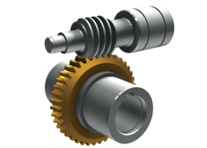
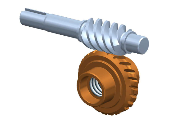
In a worm screw and gear setup, the gear ratio is determined by the number of teeth on the worm wheel (gear) and the number of threads on the worm screw. The gear ratio represents the relationship between the rotational speed of the worm screw and the resulting rotational speed of the worm wheel. The formula to calculate the gear ratio is as follows:
Gear Ratio = Number of Teeth on Worm Wheel / Number of Threads on Worm Screw
Here’s a step-by-step process to calculate the gear ratio:
- Count the number of teeth on the worm wheel. This can be done by visually inspecting the gear or referring to its specifications.
- Count the number of threads on the worm screw. The threads refer to the number of complete turns or helical grooves wrapped around the cylindrical body of the worm screw.
- Divide the number of teeth on the worm wheel by the number of threads on the worm screw.
- The result of the division is the gear ratio. It represents the number of revolutions of the worm screw required to complete one revolution of the worm wheel.
For example, let’s say the worm wheel has 40 teeth, and the worm screw has 2 threads. Using the formula, we can calculate the gear ratio as follows:
Gear Ratio = 40 teeth / 2 threads = 20
In this case, for every full revolution of the worm screw, the worm wheel will rotate 1/20th of a revolution. This indicates a significant speed reduction, resulting in high torque output at the worm wheel.
It’s important to note that the gear ratio calculated using this formula assumes an ideal scenario without considering factors like friction, efficiency losses, or the pitch diameter of the gears. In practical applications, these factors may affect the actual gear ratio and performance of the worm screw and gear setup.


editor by CX 2024-03-11